I recently purchased a used TTC450 router to do a few small projects that are difficult or impossible with the lasers. Here is my description and instructions on various aspects of the machine. You can also find some useful information in this Facebook user group.
If you consider a modification to the control board to make it Estlcam-compatible, read the section further down below for details.


Setup
I didn’t have to assemble most of the machine myself, as I bought it second-hand. However, you can see in various YouTube videos that you should take another close look at the springs in particular to reduce the backlash on each spindle. They were also loose on this machine, which led to jumps in the movement. You should check this carefully on all axes (X, 2x Y, and Z) before assembling the machine. I had to disassemble it almost completely afterward. The assembly instructions can be found here.

Here is the official assembly video:
If you want to calibrate the mechanics after assembly, you can do this with this file, for example: Download (DXF).

Software
The milling machine can also be controlled via the screen. All essential functions such as homing, zero-point setting and probing can be carried out. However, it is rather uncomfortable overall. It is therefore better to switch to a proper CNC controller. If you would rather not spend too much money here and still want to use very sophisticated software, I would recommend Estlcam. This allows the GCode files to be generated with little effort and quite intuitively (also to control many machines directly, but the cheap mainboards from the laser class are rather poor). You then need a GCode transmitter, for example Candle or Universal GCode Sender. Update: another great piece of software is gSender. It’s even more tuned to be used with a CNC. Another powerful tool is OpenBuilds Control. You can also use professional tools like Fusion 360 to control your CNC.
Update: I recently changed the mainboard to an MKS DLC, which enables direct Estlcam control of the CNC. So after creating the DXF, I only use Estlcam for the rest of the process. See some sections below.
My personal workflow is was:
- Create DXF in LightBurn
- Open DXF in Estlcam and define milling parameters, save GCode
- Open GCode in Universal GCode Sender or gSender and run.
At first glance, this looks more complicated than it actually is. The LightBurn team is currently working on MillMage, a version of LightBurn for CNC milling. When the program is fully developed, it will combine the entire workflow in one tool. If you also want to control the milling machine directly via Estlcam, you have to change the mainboard, see below.


Remote Control
There are various ways in which the milling machine can be remote-controlled. And very different approaches. Here are a few that work differently:
- As delivered, a web interface is integrated in the firmware. This can be achieved in two ways: either you connect the laser to your home WIFI, or you use a cell phone/tablet/control computer to connect to the WIFI that the milling machine creates itself. This normally means something like “MKS DLC32” or similar. The password is “12345678”. The laser can then be reached under the IP 192.168.4.1 (simply enter in the browser). If you have connected the laser to your own WIFI, you must read the IP address from the display or look it up in the router.
- The control software offers a remote control option. This is the case with gSender, for example. You can activate the remote control function in gSender, then log in to the computer on which gSender is running and get an optimized interface for controlling the CNC. gSender remains connected to the milling machine with a USB cable. Instructions for gSender.
- You use tools such as Microsoft Remote Desktop to dial into the control computer and control the milling machine as if you were sitting at the control computer.


SD-Card
If there are problems using the SD card, the following points may help:
- The SD card should be as small as possible. A maximum of 4GB is best, 512 MB is also good (the small controllers cannot handle giant memories very well)
- File names should not be longer than 8 characters
- File names should not contain any special characters or spaces
Settings
This is one of the biggest questions, especially for beginners, as to which parameters should be used for the milling processes. As with lasers, there is no general answer here, it depends on the material, cutter, software and project. There are a number of websites with information on this, in particular, good milling cutter manufacturers should also provide information on speeds. A good example of this is Sorotec, whose website contains a wealth of information on parameters, as well as a calculator and even an app for cell phones. You can get an initial idea of the parameters here.

As a user of the TTC with 500W spindle, you will immediately notice that most of the rotation speed specifications are significantly higher than the spindle’s capabilities. The 500W spindle offers speeds of up to 12,000 rpm, while most of the specifications for the milling cutters use 24,000 rpm or more. It can therefore be assumed that the 500W spindle should generally be run at full speed and not regulated any further.
Note, the speed of the 500W spindle in the normal configuration can NOT be controlled by software. The spindle’s power supply unit is only connected to the mainboard via a relay. Since it is a 24V relay, it should switch as soon as the voltage at the input is above 12V, i.e. 50% speed setting in the software. The easiest way is to always set the maximum speed in the control software. The speed can only be regulated via the potentiometer on the front of the power supply unit. However, as you have no feedback as to how fast the spindle is actually turning, you should always leave this at maximum.
The TTC offers a maximum speed of 800 mm/min in the standard setting. Here, too, it is therefore more in the lower range. Depending on the material, you also have to test which speeds work here; with larger, more stable milling cutters, you can also approach 800 with soft materials. With small, thin milling cutters for engraving, it can also be 200 mm/min.
On YouTube, you will find many videos explaining the speed and other parameters very well. Here is one example:
Probing
Another frequently asked topic is how to use the probe (the sensor for detecting the surface position) correctly. Basically, only one command is required, it is:
G38.2 Z-80 F100This command moves the z-axis a maximum of 80 mm downwards and checks whether the probe sensor is activated. If this is the case, the machine stops. If you now know how thick the sensor is (in this case I measured 19.2 mm), then you know that the current position is exactly 19.2 mm above the surface. For this, I used the command:
G92 Z19.2This sets the position of the z-axis to 19.2 mm. If you now move the laser to the 0 position of the z-axis, you are exactly on the surface of the workpiece.
I have saved a macro in UGS for this purpose. With the Z+1 macro, I move the z-axis up by 1 mm to be able to remove the sensor better. These macros can definitely be optimized. These were my first short tests.


Touch plate
As an alternative to the simple touch sensor, you can also use a touch plate that not only detects the z-position, but also the position and orientation (angle around z) of the workpiece. Estlcam already has a built-in function for this. Watch the video for a brief explanation.


I have fitted the supplied probe plate with a new cable that has a JST SM 2.5 connector so that it can be connected to the existing probe connector.
In gSender, you can also configure the use of a touch plate rather easily:

There is also a possibility for FluidNC, the functionality, but then via macro. This is explained in the following video:
Here is the code from the macro. In this macro, the plate has a thickness of 6.5 mm and an x and y distance of 10 mm. The cutter is 2 mm thick here, so the calculation includes 11 mm. The values must be adjusted accordingly at the three marked points.
;Z-Probing:
M3 (MSG Z-Probing)
G38.2 G91 Z-30 F200 ;Fast Z-Probing
G0 Z3 F5000  ;Lift Z again to 3mm
G38.2 G91 Z-10 F50 ;Slow Z-Probing
G92 Z6.5 X0 Y0  ;Reset Coordinates but with probe Thickness for Z <----
G90   ;back to absolute coordinates
G0 Z20 F5000  ;Lift Z to 20mm Axis

;X-Probing:
M3 (MSG X-Probing)
G0 X30 F5000  ;Move X 30mm
G0 Z2 F200  ;Lower Z Again
G38.2 G91 X-30 F200 ;Fast X-Probing
G0 X3 F5000  ;Move X for slow probing
G38.2 G91 X-10 F50 ;Slow X-Probing
G92 X11   ;Reset X Coordinate (Tool Radius + Probe X side Thickness) <----
G90   ;Absolute coordinates
G0 X15 F5000  ;Move X for clearance
G0 Z20 F5000  ;Lift Z to 15mm Axis
G0 X-15 F5000  ;Move X Back for Y Probing

;Y-Probing:
M3 (MSG Y-Probing)
G0 Y-30 F5000  ;Move Y 30mm
G0 Z2 F200  ;Lower Z Again
G38.2 G91 Y30 F200 ;Fast Y-Probing
G0 Y-3   ;Move Y for slow probing
G38.2 G91 Y10 F50 ;Slow Y-Probing
G92 Y-11  ;Reset Y Coordinate (Tool Radius + Y Probe side Thickness) <----
G90   ;Absolute coordinates
G0 Y-15 F5000  ;Move Y for clearance
G0 Z20 F5000  ;Lift Z to 15mm Axis
G0 X0 Y0 Z10 F5000 ;Move to 10mm above origin
Mainboard
The mainboard is the MKS DLC32, which is also very common for lasers. Therefore, the information from the other Wiki articles relating to the board also applies here to a large extent. The 3.5-inch display is also included. The drivers are standard, inexpensive A4988 driver chips. The chips are cooled by an active fan built into the lid. The machine can therefore also be heard in standby mode.


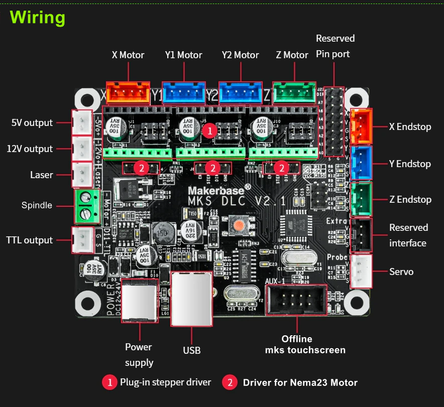
External stepper drivers
If you want to add external stepper drivers to have higher power at the motors or exchange them with Nema23 steppers, you can also connect them to the DLC32 board like this (not yet tested, since I don’t own any external drivers):

500W Spindle
Here is some more information about the 500W spindle. According to the specifications, it should reach 12,000 rpm, according to my measurements, it only reaches 10,600 rpm. I have plotted my measured values in the following picture:

Here is the connection diagram:

As you can see in the circuit diagram, the spindle is controlled by the mainboard via a relay and is therefore NOT adjustable! This can only be done manually via the potentiometer. You could replace the power supply unit itself with one that has a 0-10V input, and then control this via the spindle input. However, I’m not sure whether you have to be careful that the spindle output supplies up to 24V, which is well above the 10V. Either you can only control the output up to 40%, or the spindle always runs at full speed from 40%.
Firmware
As this is the well-known MKS DLC32 board, you can also get the firmware directly from GitHub. You can also replace the spindle with a laser and use the entire system as a diode laser. To accomplish this, the firmware must be changed, there are two variants:
- CNC firmware: https://github.com/makerbase-mks/MKS-DLC32/tree/main/firmware/TS35/CNC/Normal/Board_v2.0
- Laser: https://github.com/makerbase-mks/MKS-DLC32/tree/main/firmware/TS35/Laser/Normal/Board_V2.0
You can also download the firmware directly from TwoTrees: Download directory. It is probably also advisable to start with the firmwares provided there first, as at least the CNC firmware has a newer date in the file name than in the MKS repository. TwoTrees also provides all the tools as well as the standard firmware settings.
As usual, use the MKS Flash Tool for flashing, which is also available in the TwoTrees download directory or on the firmware page. There you will also find instructions on how to flash. It works identically to the 32bit laser mainboards.
Settings
The table shows the standard settings for CNC operation. For laser operation, you should at least change the following values (which will probably also be the case with the laser firmware, but I have not yet tested this):
$30 = 1000
$32 = 1
Standard Firmware-Settings (CNC)
| Number | Value |
|---|---|
| $0 | 10 |
| $1 | 25 |
| $2 | 0 |
| $3 | 7 |
| $4 | 0 |
| $5 | 1 |
| $6 | 1 |
| $10 | 1 |
| $11 | 0.010 |
| $12 | 0.002 |
| $13 | 0 |
| $20 | 0 |
| $21 | 1 |
| $22 | 1 |
| $23 | 7 |
| $24 | 300.000 |
| $25 | 800.000 |
| $26 | 250.000 |
| $27 | 1.000 |
| $28 | 1920.000 |
| $30 | 10000.000 |
| $31 | 0.000 |
| $32 | 0 |
| $38 | 1 |
| $40 | 1 |
| $100 | 800.000 |
| $101 | 800.000 |
| $102 | 800.000 |
| $103 | 100.000 |
| $104 | 100.000 |
| $105 | 100.000 |
| $110 | 800.000 |
| $111 | 800.000 |
| $112 | 800.000 |
| $113 | 1000.000 |
| $114 | 1000.000 |
| $115 | 1000.000 |
| $120 | 400.000 |
| $121 | 400.000 |
| $122 | 400.000 |
| $123 | 200.000 |
| $124 | 200.000 |
| $125 | 200.000 |
| $130 | 450.000 |
| $131 | 450.000 |
| $132 | 80.000 |
| $133 | 300.000 |
| $134 | 300.000 |
| $135 | 300.000 |
FluidNC-Firmware
FluidNC is an alternative firmware for lasers and CNC machines that has some advantages over the grbl firmware. It can be seen as a further development of grbl, which has not been developed for several years. FluidNC runs on 32-bit controllers such as the ESP32 and offers both WLAN and Bluetooth interfaces (in addition to USB). There is also a web interface and SD cards are also supported. However, the display is not!
One of the advantages of FluidNC is that the configuration is done via a YAML file, the settings of which are applied after a restart. Therefore, no flashing is necessary to change parameters.
I have created the appropriate configurations for both CNC and laser operation and you can switch between laser and CNC just by changing the configuration and restarting the controller. In addition, it is much easier to fine-tune the parameters than with grbl. Download the settings.


You can then switch between the configurations via the web interface as shown in the images, or simply via the console:
#new configuration:
$Config/Filename=config_cnc.yaml
#reboot:
$Bye
Addons
I have created a few little helpers to hold workpieces in place, for example. As I’m only doing small tests, a bit of plywood from which I laser-cut the corresponding shapes is sufficient. The files contain both the LightBurn project file and the SVG version, e.g. to mill them out yourself with the milling machine: Download.


Ingo has constructed another series of stops: Download (STL files).


Contacts / plugs
The connectors used on the mainboard are JST XH 2.54 connectors (four-pin for the motors, three-pin for the limit switches). The connectors for the push-button sensor or the laser module are JST SM 2.5 plugs/sockets. If you often use such plugs, you should get a set including crimping pliers, then you are prepared for the next tinkering.
Mainboard / Estlcam conversion
Many users decide to convert the router so that they can operate it directly with Estlcam. As Estlcam does not currently support 32-bit boards, you have to look for a mainboard of the older 8-bit generation. A simple and common solution is to convert to an Arduino Uno or Nano with a CNC shield. There are several instructions and descriptions for this. In this case, however, I find it much more convenient to convert to an MKS DLC (without 32), as the size and position of the connectors is very similar and not much needs to be converted. And no additional components are required (e.g. for the drive of the 500W spindle). The board also fits directly into the old housing with the old screws. Overall, there are only two disadvantages from my point of view: The DLC board does not have a switch, which means that the board is always on as long as the power supply is plugged in. This means that both the power switch and the emergency stop no longer work! Here you have to think about something else, such as integrating the emergency stop into the supply line to the power supply unit or in front of the housing plug.


As I still have use for the old board (it will be needed again later for the Millmage tool), I printed a new housing that is almost identical to the old one. I redesigned this case: https://www.thingiverse.com/thing:4505741 and added the appropriate holes for cables and fasteners. You can download my version here. You might also be able to adjust the position of the fan in the lid a little, but I left that for now. Installation and wiring are very simple, all connectors fit almost exactly as on the DLC32 board. Then just connect the power supply and USB (if you don’t want to move the motors, just USB is enough, then the controller is already online) and you’re done. I then made the following settings in Estlcam:


This means that the control system basically works. The tuning is still pending, so I will do a few test millings.
In principle, the screen is lost with all conversions of this type. The screen supplied is only supported by the original MKS firmware. With the DLC mainboard, however, there is the option of using a display with rudimentary operating options and even an SD card slot, the MKS TFT 24 or MKS TFT35 (note, NOT the MKS TS24 or TS35 displays!). This display uses its own controller and controls the mainboard as normal via the serial interface (directly UART instead of via the USB chip). It can therefore be used on all boards that have a UART interface (i.e. all of them) and have made it accessible (possibly not all of them). Note: this doesn’t work while the Estlcam firmware is used.


Changing the stepper motor drivers
If you also install new drivers as part of the conversion, I have created a list of microsteppings for various drivers here. Experience has shown that 1/16 steps work well with the standard settings. If you want to increase the speed even more, you may need to reduce it to 1/8 steps so that the controller can still keep up. However, I have not yet tested this myself.

The calculation of the settings in Estlcam or other software is as follows (in the example with 1/16 increments, as in the as-delivered state):
Normal Nema17 motors were installed, with a resolution of 1.8°. This results in 200 steps for one revolution (360 / 1.8). The spindles of the drives have a pitch of 4 mm / revolution. The 200 steps therefore move the mechanism by 4 mm. Conversely, this means 50 steps per millimeter. If these 50 steps are now divided into 16 microsteps (A4988 driver and all jumpers bridged, or all sliders ON at the DLC32), this results in 800 steps per millimeter (50 × 16). This value can also be found in the original firmware in the parameters $100-$102. If you have changed something here in the mechanics or the microsteps, you have to calculate this analogously.
In Estlcam you can enter the value in different ways. In the following image, the settings are equivalent!

Hardware emergency stop
As the DLC mainboard does not have an integrated switch, as already described, the switch or emergency stop must be installed in the supply line. This can easily be done by integrating an emergency switch into the power supply line. If the power supply is cut here, all motors are de-energized, the small spindle is also de-energized and the relay that activates the 500W spindle is switched off.


Software emergency stop
Estlcam also offers the option of performing an emergency stop / emergency shutdown via a connected switch. However, this is only to be understood as additional safety and does not replace a real hardware emergency stop in the power supply! If the software stops responding, the emergency stop will also stop responding! With the MKS DLC mainboard, you have the option of creating up to three additional switches. These are connected to A0 to A2 on the mainboard. In Estlcam you can then assign them as inputs 4 to 6 (the other inputs are already occupied by the limit switches and the push-button sensor). I connected a small push-button with a Dupont connector to input 4 as a test. See pictures.


Relay control using Estlcam
There is also an output on the DLC that Estlcam can control directly, namely pin A3. This is switched from 0V to 5V when activated. This can be used to control a relay, which can be used to control the extraction, ventilation, or something similar. This is completely analogous to the descriptions for diode lasers here: Connecting a relay.
NumPad for Estlcam
Estlcam makes it possible to control the movements of the milling machine via the number field on the keyboard. With an external (USB or Bluetooth) numeric keypad, you can even use this as a remote control directly on the router. There are also ready-made sticker sets for labeling. However, you can also quickly print them yourself on self-adhesive film or labels and cut them out. Ingo has also created a holder with which the number field can be attached. Download (STL). The stickers from the pictures are available here, and the keypad here.


Tips and Notes
Here I collect a few more tips and hints that I have gathered during use. These are often tips from experienced users, whose knowledge I am happy to record here.
Finishing with the same milling cutter
If you cannot mill out an object in one pass (which is probably the rule), it can happen that you can see the different layers or passes afterward. To avoid or remove this, you can make a second pass for “sanding” or “finishing” after rough milling. If you don’t have an extra milling cutter for this, you can simply use the milling cutter you are currently using. To save yourself the effort of making a second setting, you can integrate a finishing pass in Estlcam. To ensure that the finishing cutter does not cut the same layers as the first pass, you have to create the cutter again with the same properties, but with the maximum depth infeed that it allows (or that is at least necessary for the object). In my case, the board was 18 mm thick, so I set the infeed to 20 mm. This immerses the cutter as far as it has previously cut in several passes. Then it moves a little (0.1 mm in the screenshot) closer to the object and grinds the outer edge again. In my case, 0.1 mm was already very close, you should probably start with 0.2 mm, as Estlcam also suggested for me. 🙂


Results / Projects
Here are a few examples of work with the TTC450, and I’m sure there will be more to come over time 🙂 The first test was a recess for a magnet that was to be inserted into a laser-cut template.


Videos / Reviews
Here are a few more videos and reviews of the TTC (if you want me to add any more, just let me know):