Adding limit switches / end stops – automatic homing
Notice
Most current series have new firmware that usually does not need to be re-flashed and should work right away. Especially the S30 (Ultra) series as well as the latest S9 lasers with 32bit-boards. Try without flashing first!
For older models, adding end stop switches and thus enabling home requires flashing a new firmware to the controller that has homing enabled. For a Sculpfun laser, I strongly recommend using the firmware that I created, “1.1h_S6S9”. Alternatively, us can use the firmware “1.1h custom, XY homing”, that can be flashed easily via LaserGRBL. See the firmware update page for details. If you do not use this firmware, you might have different coordinate system values, as described in the following text. See the last section of this page in this case.
If you are struggling with the coordinate systems that are mentioned in the following, I recommend reading the article about laser coordinate systems.
This is one of the most recommended topics because it makes the use of the laser MUCH easier. Automatic homing means that the laser head is moved to the same position at every start. Hence, you can use an absolute coordinate system in your workspace. You can do a job, leave the object in place, shut down the system, come back tomorrow and can add another job at the exact position. The firmware is already prepared to use limit switches, the control board as well. The following pictures show how to connect those switches. You can get additional information about this topic in the reprap.org wiki or grbl documentation.
Note
Limit switches are not absolutely necessary for operation. They simplify the work in some cases, but you can also get along perfectly without them. You can also create various other tools to obtain the same effect, see also the article on coordinate systems.
Sculpfun limit switch kit
Sculpfun now provides a kit to add limit switches to the S9 / S10 laser models. The S30 series has switches already included. You can find the kit at official stores and the official homepage: https://sculpfun.com The official installation video can be found at the end of this page.


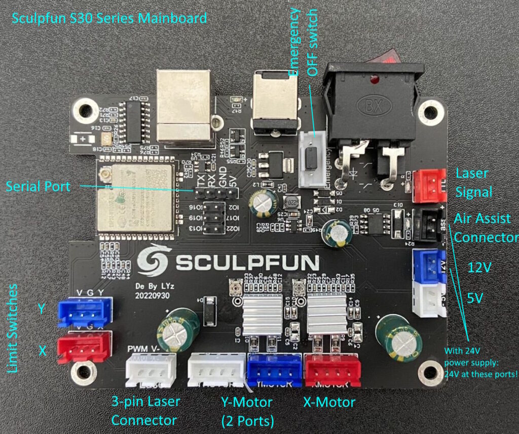
Electrical connection
The connectors used at the mainboard are JST XH 2.54 plugs.


I sometimes read articles that tell you to cut one of the wires of the end stop switch. This is NOT required (usually, see following remark). As long as you connect the correct pins, you don’t need to change anything electrically. If you use the standard configuration of the grbl firmware, the signal pins for the end stops have an internal pull-up resistor activated. Hence, the controller reads a logical 1 if nothing is connected. The attached switch has to tie the pin to ground in order for the controller to read a 0. So, basically, the type A connection from the figure above is sufficient. Most of the switches you can buy online include the circuit following type C (“Makerbot Design”). You can directly connect them (as long as the pins fit) and don’t care about the positive wire. If you cut it, you will also lose the LED function showing if the switch is pressed.
Notice – switch board wiring
I recently found out where the above tip about the positive pole of the switch being cut comes from. If you use limit switches that use the circuit according to the schematic type C (picture above, right), but they are not assembled, it can lead to problems depending on the mainboard. Especially with 32bit boards that use 3.3V as system voltage. If a Type-C switch is not assembled, the VCC line is directly connected to the signal output (as long as the switch is not pressed). This causes the boards to crash or creates an overload on the input pin. Therefore, the VCC line must be disconnected here. If the switch is fully populated, then this is not an issue, as the R/C circuitry will not allow the problem to occur.
So: with switches like (1) in the picture the VCC line must be disconnected, with switches like (2) (fully equipped) you don’t need that!
I always recommend choosing equipped switches because they provide a better / cleaner signal and also give an optical feedback by the LED, if they were operated.
Additional remark: users also reported full equipped switches that short the laser anyhow. I suspect a different schematic at those switches. So, if you have a fully equipped switch and still short the laser – disconnect the VCC line. It’s worth a try.
Physical connection
Mounting brackets
I have quickly designed brackets that can be used to attach the switches to the frame. I uploaded them on Thingiverse: https://www.thingiverse.com/thing:5158550 (S6/ S9) and https://www.thingiverse.com/thing:5392586 (S10). However, they only fit the type of switch I use. But there are various brackets for almost all switch types at Thingiverse. Here is another set of mounts for another type of switch (longer circuit board): Download (LightBurn file). Here is another set for 3D printing: https://www.thingiverse.com/thing:5504235 (designed by Tor from the Sculpfun User Group at FB). If all of those don’t fit, search Thingiverse for other models, there are plenty.
The next step is to plan where to mount the switches. Basically, we have two dominant variants people use:
- A: Less convenient cabling, easy coordinate system handling (switches at P0/2 and P4)
- B: Easy cabling, coordinate system brain fuck (see image, switches at positions P0/2 and P5)
- Additionally, you can use any combination you like because you can configure the firmware and software accordingly.
Personally, I went for option A. But I will also consider option B in the explanations.

As mentioned in the documentation of LightBurn, the software always uses the internal coordinate system as a positive coordinate system starting in the bottom-left corner (P0). If you are finished with the homing setup, you want the laser to use the same coordinate space as LightBurn.
For option A, you connect the end stop switches at the front of the rectangular frame (either left or right side of the frame, P0 or P2) and left side of the moving gantry (P4). This makes the laser also home in the front-left position, which is the same as the LightBurn origin. Hence, you don’t need to calculate anything with coordinate systems, after homing, you are done.
For option B, you connect the switches to the front (P0 or P2) and the right side (P5) of the X-gantry. After homing, the laser head is at the front-right position. As you notice, that is not the same as the origin in LightBurn. That’s why we need to do extra work later on. The same holds for rear-right and rear-left positions. Follow option B in this case.
Mount the switches
Since numerous types of switches are available, it is hard to give exact advice on how to physically mount them. If you search on Thingiverse for mount brackets, you will probably find one that matches your switch. If you use option A, you have the problem that the switch needs to be connected to the moving X-gantry and passing the cables along the moving laser head. My solution is to put the cable into the aluminium profile and fix them with an aluminium profile cover / seal that I had at hand.


Checking physical function of switches
Before you command your laser to move, you can test the correct function of the switches. By typing a question mark (“?”) into the console, you get the status of the controller. Look out for values starting with “Pn” (Pin status). If no pin is active, this field is completely missing. If a pin is active, the assigned axis / port is given.

In the screenshot above, you see three different situations. First line: two pins are active: Y and D. “Y” is the limit switch of the Y axis. D is a limit switch at the door, which is a safety feature I enabled (see documentation on this page) and most likely not present at your output. The second line shows no active homing limit switches (except my door that was open). The third line is the output with no active switches, the “Pn” section is completely omitted.
If you are finished with your wiring, you should test this output. It should be empty if you don’t press any switch and should contain the correct letters, when you type “?” while activating the switches.
If this is inverted, meaning that it shows all switches active (“Pn:XY”) if you don’t activate a switch and the letters disappear if you close them, you have inverted limit switches. This is nothing serious, you can configure grbl to invert the logic by programming $5=1.
Firmware settings
We now need to tell the firmware that it should do homing and in which direction. This is done using the parameters $22 and $23 (grbl documentation). $22 will tell the firmware that homing shall be enabled (only works if firmware has homing enabled, see firmware notice). So, you have to set $22 to 1. This can be done in the console window by typing “$22=1” and pressing enter, or using the graphical machine settings window. The more interesting parameter is $23. This parameter defines in which direction the switches are searched for by the homing algorithm. The following table defines how to do it.
Excursion: Firmware settings
Since the limit switches can be at any position for each axis (either at the minimum or maximum position), you need to tell the firmware, in which direction the firmware should search for it. “Normal” means moving into the positive direction, which is backwards and right. “Inverted” means going to front and left (against the direction of the coordinate system arrow). In our case, we don’t have a Z-axis, so we don’t need to consider the last column.
| Setting Value | Mask | Invert X | Invert Y | Invert Z |
|---|---|---|---|---|
| 0 | 00000000 | N | N | N |
| 1 | 00000001 | Y | N | N |
| 2 | 00000010 | N | Y | N |
| 3 | 00000011 | Y | Y | N |
| 4 | 00000100 | N | N | Y |
| 5 | 00000101 | Y | N | Y |
| 6 | 00000110 | N | Y | Y |
| 7 | 00000111 | Y | Y | Y |
As you now have (I’m sure you have) found out by yourself, you need to set the parameter to 3 or 7 (option A) or 2 / 6 (option B). [If you put the switches rear-left: 1 or 5; rear-right: 0 or 4] The reason you can choose two values are that you don’t have to care about the Z axis. Where do those values come from? For option A, the firmware has to search for the X switch to the left, which means a negative direction. The same holds for the Y switch which is at the front, negative direction as well. So, you need to select a value that is inverting the direction of search (a “normal” search would go into positive direction). Option B lasers must search for the X switch to the right (positive, not inverted) and look for the Y switch to the front (inverted as with option A). If you check the table for these movements, you will find the values you have to use. Again, program them into the firmware memory be typing “$23=(your value)” in the command line or using graphical interfaces. As you can see here, you can have any combination of switches, you just need to use the correct value here.
When you are done configuring, you can test your setup. I recommend to hold one finger above the power switch of the laser in case it starts to move in the wrong direction, you can shut it down. Then click on the Home-button in LightBurn. If everything is working fine, the laser starts its homing sequence and finds its home position. You might need to adjust the position of the switches to get the perfect results.
Workspace size
You need to know your workspace size exactly. At least if you want to use all space. You can declare a smaller workspace if you like, but a larger one will cause the laser to crash into the frame. If you have a Sculpfun laser and just want to use “most of it”, you can use 400 x 400 mm. You can increase this a little, but you have to test how far you can actually travel.
The workspace size is set via parameters $130 (x) and $131 (y). grbl uses this information to calculate the coordinates. That’s why it is important to set these parameters.
If you notice a deviation between your provided workspace size and the position after homing, check the parameter $27. This is a pull-off distance after homing. If you set this to 1 mm, your laser will be placed at [1,1] or [-399,-399] respectively, after homing.
Setting origin
If you used option A, you are done now. Option B or any other option, read on. If you are using any other combination of end stop positions, your laser might be either positioned front-right, back-left or back-right. In this case, you need to tell the firmware that there is an offset between the machine coordinate system and the workspace coordinate system. This is also explained well in the LB documentation. The command you need is “G10 L2 P1 xx yy”. (There is an even simpler command available, see section below) This command tells the system to use an offset in the first coordinate system by xx and yy mm. Here are my suggestions for this setup [I did not test all of them myself, so please let me know if it is working or not]
- Laser front-right: “G10 L2 P1 X-400 Y0” (you need to replace 400 with the size of your workspace, the difference between total left and right positions)
- Laser back-right: “G10 L2 P1 X-400 Y-400”
- Laser back-left: “G10 L2 P1 X0 Y-400”
You need to set this every time the laser is powered on. So, you should create a macro button in your control tool (which you have to press after each homing) or if you want to be brilliant, you can add this command as a “startup block” to the firmware (documentation). This tells the firmware to issue this command at every start: type “$N0=G10 L2 P1 XX YY” (using your values for x and y) into the command line to save this block into firmware memory.
The information I stated before is wrong. The parameters that are set by the G10 command are saved in the EEPROM memory of the controller and therefore NOT lost by a reboot. So, you don’t need to set them more than once (nevertheless, the startup block thing I mentioned above is nice to know 🙂
Alternative: There is an even easier command that can be used to save the offset: “G10 L20 P1 X0 Y0”. This command does not require manual parameters set for the x and y coordinates. After homing, you just move the laser head to the front left position using the move controls from LightBurn or LaserGRBL (do not move the head using your hands). If you arrived at this position, issue the command “G10L20P1X0Y0” in the console. This command takes the current position and calculates the offset automatically. So, you don’t need to handle values manually. If you ever want to reset the values you saved via these commands, issue “$RST=#” in the console.
Note from LightBurn documentation: If you enable a workspace offset, you will also need to make GRBL report its location relative to this shifted origin, instead of in “machine space” by setting $10=0.
So far, I could not test every combination, I would like to know if it is working for you. Please leave a comment or mail to tell me your experiences!
Tuning
- You can configure LightBurn to automatically home once started, so you don’t have to care about that.
- You can additionally tune your homing, e.g., by adjusting the speed the laser moves until the switches are found (parameters $24 and $25). Don’t go too fast; otherwise the system can’t stop in time when the switch is triggered. I use $24=75 and $25=1000.
- If you want to have the highest precision and repeatability, you should set $1 to 255. Then the motors will be powered continuously and can’t lose any micro-steps in the moment of disabling. It also avoids the possibility of manually moving the laser head accidentally. Be aware that constant power to the motors might lead to increased temperature of either the motors and the driver chips. I recommend only using it if you don’t have long idle times of the laser.
Hard- and Soft Limits / Workspace limits
The following two parameters have NOTHING to do with homing! For homing, both parameters can remain set to 0. This is often lumped together, but it is something entirely different. You could also home to the center and go in all directions from there. Therefore, one is not prevented from doing so. What you still need/want now is protection for the workspace. These are the soft or hard limits. With these, you tell the firmware that it is not allowed to drive over certain limits. In the standard case with two limit switches for homing, you use the soft limits ($20). With this, the firmware takes the zero point of the reference and adds the set working space size to it. Then, when you want to move out, there is an alarm, and it stops. Hard limits ($21) have the same effect, but again use end stops as limits. If you have only the two limit switches attached, as described above, it’s like fencing off a rectangular garden on two sides and hoping no one can escape.
- Soft limits ($20): If you enable soft limits, the controller will prevent hitting the frame with the laser head. This requires to have set the correct workspace size (parameters $130 and $131). Since the controller knows the [0,0] position after homing, it can use the [xmax,ymax] information to check if a command will drive the laser out of bounds. In this case, the laser will stop and issue an alert. I recommend turning this option ON.
- Hard limits ($21): If you enabled hard limits, the laser will stop upon hitting the end stop switches. Since most users only put switches to one end of the axes (where you want to home to), there are no end stop switches at the other ends. So in my opinion, it does not make much sense to enable this feature. It also doesn’t hurt if you do, but if you have enabled soft limits, you should never reach a situation where you need this. Ok, except you move the laser manually and the laser lost its correct position. But it will still only help in one direction. It is possible to add limit switches to the other ends as well, they can be wired to the same ports.
If you want to use hard limits on all sides, you can just wire additional switches in parallel to the existing ones. It doesn’t matter on which side the limit was reached, so the laser doesn’t need to know which one was pressed. Only that a switch was pressed is relevant.

Alarm 8 or Alarm 9: Homing fail.
If you get Alarm 8 “Homing fail. Cycle failed to clear limit switch when pulling off.”, in most cases it is because the limit switches have to be inverted. The firmware recognizes the switches as permanently pressed and therefore cannot start a homing cycle. In that case, parameter $5 must be changed to 1 (or back to 0 if it was 1). Then the error should disappear.
If you get the error 9 “Homing fail. Could not find limit switch within search distances. Try increasing max travel, decreasing pull-off distance, or check wiring.”, then the laser does not recognize the switches. They are either connected the wrong way round or are not detected electrically at all. Therefore, check manually as described above whether the switches are detected at all. You must get Pn:X if the x switch is pressed and the same for y (Pn:Y).
Using standard firmware
It might not be required to flash the modified firmware version to enable the homing functionality. Though, this has consequences:
- After homing, the coordinates of the laser are not set to [0,0]
- Homing is done one axis after another, which takes much more time than the modified firmware version, where both axes do the homing cycle at the same time.
- If homing does not work at all, you have the complete standard version of grbl, where it first tries to home the z-axis. Since there is none in most cases, homing will fail completely.
Laser coordinates
If you use the standard firmware, grbl treats the machine coordinate system as a common CNC coordinate system. That means, the [0,0] position is ALWAYS top-right. If you change the position of the limit switches as described above, this will lead to the following positions (imagine a workspace setting of 410 × 400 mm):
- top-right: [0,0]
- top-left: [-410,0]
- bottom-left: [-410,-400]
- bottom-right: [0,-400]
Therefore, you need to calculate the offsets differently. I suggest using the “easy” command you learned before: “G10 L20 P1 X0 Y0”. This should do everything you need. You can also use the other command, which is straightforward in this case because the offset is the one you are seeing. Example: if you have homed to front-left, the command would be: “G10 L2 P1 X-410 Y-400” (you need to use the exact values from the list above).
Videos
Here are some videos, that might help if you better like watching than reading 🙂 I highly recommend reading this page before to get the background knowledge that is needed.