In the forums, there are often discussions on how to improve the quality, especially of lasered images. Many users have problems with so-called banding and skipping, i.e., visible lines in the image. In most cases, these can be traced back to incorrectly set mechanics (see here) and incorrect image laser settings / technique (see here). Once you’ve done all that, you can get one last bit of quality out of it by replacing the stepper motors and the pulleys. This optimizes the movement of the laser. However, the laser (at least with 8-bit boards) will no longer reach the top speeds as before, as more computing power is required. But the picture is improved. Additionally, you will mainly notice an effect on tiles or other material that can support fine detail, like mirrors or metal.
Basics
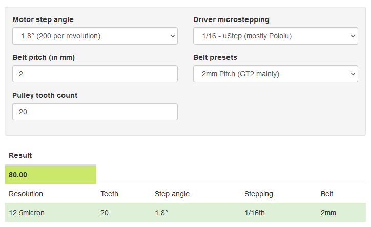
As a basis, here is a short outline of the stepper motors. They are called just like that because they are controlled in individual steps. Most stepper motors have a stepper angle of 1.8°. This means that 200 steps result in a complete revolution. The motors are controlled by stepper motor drivers. These can divide the individual steps of the motor into 16 microsteps (standard Polulu driver) by controlling the coils. This results in 3,200 steps for a full revolution. If a standard pulley with 20 teeth and a standard belt (GT2) with 2 mm pitch are used, the result is a step size of 0.0125 mm (12.5 μm or 80 steps / mm). [See calculation below]
Firmware-Setting (Sculpfun Standard):
$100 = 80
$101 = 80
The laser has a focus size of 0.08 mm. In the best case, we want to laser an image with a line spacing of 0.08 mm (=318DPI). If you now divide this 0.08 mm by the 0.0125 mm step size, you get 6.4 steps as a result. This means that the motors can not implement this 0.08 mm line width exactly. As a result, lines are either lost or have to be doubled to achieve the desired specification in the software. However, this can be changed by changing the motors and / or the pulley ratio.
Small edit: of course, you can also change the line spacing to 0.075 for example, which is very close to the focus size and results in full steps. Additionally, the focus size is never perfectly 0.08 (I guess), so you most likely won’t notice any difference in quality. Still, if you want to increase the resolution further, read on.
Modification of the pulleys
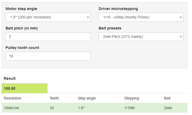
However, if you use a pulley with 16 teeth instead of the pulleys with 20 teeth, the above calculation results in a step size of 0.010 mm (10 μm or 100 steps / mm). This means that the 0.08 mm line width can now be achieved exactly (8 steps).
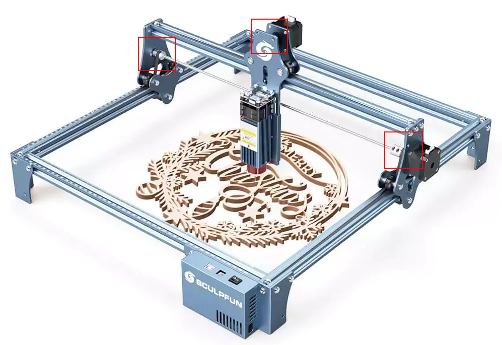
Three pulleys are required, two on the y-axis, one on the x-axis. Specifications: 16 teeth, inner diameter 5 mm, belt width 6 mm, such as this one: AliExpress-Link.
Firmware-Setting now:
$100 = 100
$101 = 100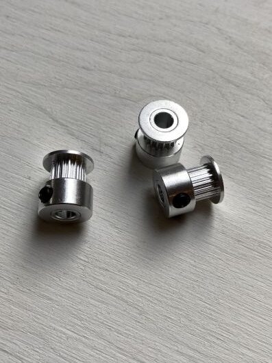
Modification of stepper motors
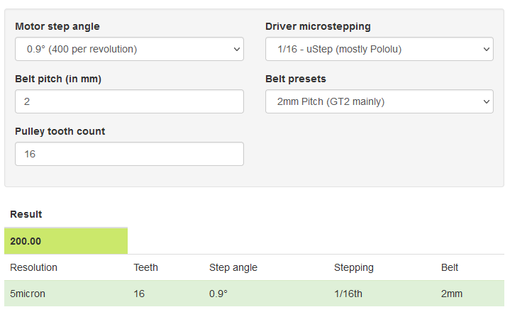
If you want to push the whole thing a little further, you can also replace the motors with stepper motors using 0.9° step size. This doubles the accuracy once again, and results in a step size of 0.005 mm or 5 μm (200 steps / mm). Still, this allows the 0.08 mm to be matched exactly (16 steps).
Firmware-Setting new:
$100 = 200
$101 = 200
However, since 200 steps now have to be carried out instead of the original 80 steps per millimeter, the small ATmega microcontrollers in the standard boards reach the limits of performance. High speeds are no longer possible. But you are more precisely on the way.
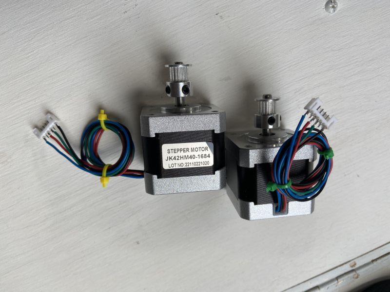
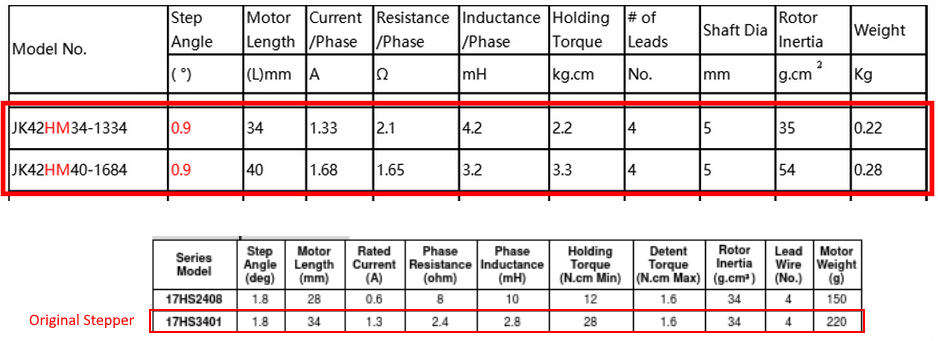
I chose stepper motors like this: AliExpress-Link. Key data: Nema 17, 0.9° step resolution. Here you should still pay attention to which technical data the motors have so that they also have sufficient power and the board can still drive them. The motors in the picture work, but I did not do an endurance test and did not adjust the reference voltage on the driver. The original engines are slightly lower in power. You can also select the JK42HM40-1634 variant, which is slightly weaker than the original motors.
Calculations
Calibration
Since no mechanics is perfect, the values of 100 or 200 steps per mm are more theoretical values. You should do a calibration of the axis, if you want to get perfect. Cut a rectangle with 100 mm size and measure the outcome. Then calculate the corrected steps setting value. The easiest way to do this is to use the wizard in LightBurn, as explained at the bottom of the mechanics setup guide.