Notice
If you are not familiar with the coordinate systems of such lasers, I recommend having a look at the brief description here.
Links to buy the extension kit are available at the resources page.
The extension kits for S9 and S10 are slightly different! Be sure to get the right one!
The S10 laser has both x and y motors mounted closely beneath each other. Only the laser is moving and requires a longer cable. At the S9, the x motor is moving along with the head and therefore requires a longer x motor cable. You can use the S9 cable at the S10 by opening the shield around the cable (violet dotted rectangle) and attach the connector to the x motor. But you can’t use the S10 cable at the S9 (without getting an extension cable for the x motor).
S30 extension kits
The S30 extension kits (especially the 900×900 kit) can’t be mounted to the S9 frame! Since the S9 uses a different drive mechanism for the x-axis, there are some parts missing to fix the x-axis motor. You can either build such parts your own or buy the linear rail kit as well (those parts are included there). The S10 can use the S30 extension kits.
If the size of the normal (already large working range of 410×420 mm) is not enough, you can expand it to twice the size of 410×950 mm with a specially adapted kit from Sculpfun. Here is a brief overview of the necessary settings to set up the software correctly after the hardware upgrade.


New: Meanwhile, new extension kits have been released that even cover an area close to 1 m × 1 m. Those also include the enforced frame version that can be used with the 20W laser module.


Mechanical assembly
The procedure is explained very simply in the official videos of Sculpfun:
S9:
S10:
S10 + S30 (new kit):
Adjustment of stepper reference voltage
Stepper motors must be operated with the correct voltage (info about this, e.g., here). For this purpose, the motor drivers offer to adjust the reference voltage. When upgrading to the large extension kit, two motors hang on the y-axis where only one motor hung before. Therefore, the setup video explains how to readjust the reference voltage. Here is the whole thing explained again as a slideshow.
Note: If you experience motor problems with the new extension kit, try to turn the potentiometer only 45° instead of 90° as shown in the video (or turn it 45° back if you already did). Some users report that they had better results using this setting. You can also measure the reference voltage, a reasonably good value should be 1.15V, this has been reported several times as quite suitable.


Software settings
Firmware
In the firmware, the new size of the workspace must be set so that the firmware can continue to offer all functionalities. This requires to check / adjust the parameters $130 and $131. In the normal use of the older extension kit, the size is just changed in the Y direction, so only this parameter has to be adjusted: $131=900 (example value). If you also extended the x-axis, you can set the new value with $130=900 (example value). This sets the size of the working area in the y-direction to 950 mm. Due to individual changes (e.g., hoses of an Air Assist), the value can sometimes vary slightly. The following table shows the common sizes of the workspace after setup:

The following screenshots show the different ways to change the settings. One of them is enough. The setting is applied permanently.


LightBurn
In order for LightBurn to be able to use the full working area, the new workspace must also be set here. The easiest way to do this is in the device settings (see screenshot). This will customize the virtual workspace. Again, usually only the “height” setting needs to be adjusted.

LaserGRBL
LaserGRBL reads the size of the work area from the firmware and, to my knowledge, has no manual setting option for the size of the work area. It therefore no longer needs to be adjusted.
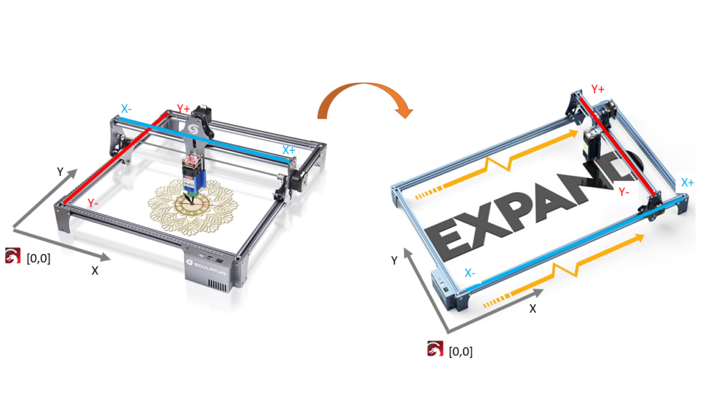
Change of the entire orientation of the laser (90°)
It is often difficult to place the laser upright on a table and look at the laser from the front. It is usually easier to place it vertically on a table. As a result, you have to rethink between the working area on the computer and the laser, as the laser is rotated by 90 degrees. You can therefore swap the axes of the laser to ease visual control.
Remark (by PY from LightBurn forum)
Note that most tools assume you are scanning along the X gantry in terms of acceleration/speeds. LightBurn defaults to 0 degree scanning as well, so just be aware. You may need to make adjustments to your settings based on this. Speeds along the X gantry will typically be much faster due to the much lower mass involved in those movements. It’s advisable to have the new default scanning direction 90° afterward.
From my point of view, the simplest way to do this is the following:
- Swapping the two connectors for the x- and y-axis on the motherboard
- Reversal of the (newly formed) y-axis
- Adjustment of workspace sizes
- [optional] Adjustment of the homing configuration or adjustment of the limit switch position
Edit: LightBurn V1.6 seems to offer the function out of the box, so no physical change is required (though, this only works for LB then, if you want to have the rotation for all other tools like LaserGRBL, you need to take the physical approach):

Swapping the plugs
You could also change the axes within the firmware, but this means a manual change to the code and compiling the firmware yourself. If you don’t like that, you can simply change the two plugs for the motors of the x- and y-axis:

Adjustment of the direction of travel of the axles
When this is done, you will notice that the former x-axis, now y-axis, is moving in the wrong direction. We can easily fix this in the firmware settings: $3=2 (if it was 0 before). You can simply enter this command in the console, and it will be saved permanently. Just check the current value you have in your firmware settings and select a line from the table below that has the same configuration but the Y axis direction inverted.
Explanation firmware setting
Setting the $3 parameter defines the direction of movement of all axes. If you want to invert one or more axes, you can see the value from the following table:
| Setting Value | Mask | Invert X | Invert Y | Invert Z |
|---|---|---|---|---|
| 0 | 00000000 | N | N | N |
| 1 | 00000001 | y | N | N |
| 2 | 00000010 | N | y | N |
| 3 | 00000011 | y | y | N |
| 4 | 00000100 | N | N | y |
| 5 | 00000101 | y | N | y |
| 6 | 00000110 | N | y | y |
| 7 | 00000111 | y | y | y |
Now the laser should behave as usual, if you control the laser with the arrow buttons, it should move correctly in all directions.
Adaptation of the working area
Finally, the sizes of the axes have to be adjusted, as now the x-axis (width) is 950 mm long and the y-axis (height) 410 mm. The parameters must be changed as described above on the page (firmware + control software) only swapped accordingly.
Optional: Adjustments for homing cycle
If you had automatic homing / limit switches installed, you should check whether the limit switches are still logically correct. The limit switch on the former x-axis, now y-axis, must be replaced to the other end (or the homing adjusted accordingly). Otherwise, the laser now references rear-left instead of front-left. If you have previously referenced to the front-right due to the easier cable routing, you now reference to the front-left. The corresponding parameters and offsets must be readjusted, see chapter limit switches.