This feature is a LightBurn-feature, not limited to any laser or camera type. See here for the official documentation: https://docs.lightburnsoftware.com/Camera/index.html. It does not work with LaserGRBL!
Update: At LightBurn LBX it was announced that the camera features get a major update soon. Calibration and all related stuff will get much, much easier. Looking forward to seeing it! 🙂
Preface. Some users have problems with the use of the camera. Therefore, I have to mention something here because I think that many approach the subject with the wrong attitude: The camera feature is technically and from the handling partly very complex! It is generally not well suited for beginners! It is basically a nice gimmick, which can make your work easier, but in 80% of the use cases you are much faster and more precise without it! I recommend everyone to first deal intensively with the laser and manual alignment, and then use the camera. This saves a lot of frustration. Hints for manual alignment can be found in this article: Coordinate systems and alignment.
A crucial requirement of the camera feature is using absolute coordinates; therefore, you need limit switches for it to work reliably!
Frequently asked questions
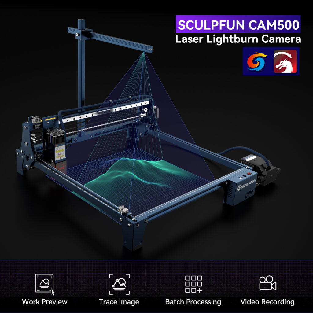
How high does my housing have to be to use the camera? The camera’s mount is 40 cm high, and the standard Sculpfun laser frame is 8 cm high. So together it is 48 cm. I would therefore recommend a housing with an interior height of 50 cm. But you can theoretically shorten the mount or mount it differently, then you can save a few more centimeters.

Can I also use the camera with the extension kits (40×90 cm or 95×95 cm)? Basically, yes. However, you either can’t cover the full area or you lose accuracy in resolution. I’d say it’s a more theoretical possibility, in practice it’s not usable with a much bigger workspace than 50×50 cm (except you only use a smaller portion with the camera). The resolution of the camera is not high enough to detect the calibration pattern reliably then. More about this below in the section on the size of the working area. If you reduce the camera function area to 400×400 mm, you can use the camera with every frame you like. However, you might need to mount the camera in front here so that this edge is definitely well in the picture.
Would it be possible to align/mount the camera differently (not only at the back)? Yes, that is no problem. You just have to make sure that when calibrating the image plane, you really click on the pattern as requested, so first make the cross at 1, then at 2 and so on. This way, LightBurn recognizes the rotation of the camera image in relation to the origin of the workspace.
Background knowledge
To be able to use the camera properly, a little background knowledge can’t hurt. Then some problems will also become clear / solvable more quickly.
Using a camera together with the laser is a relatively complex problem, even if using it looks quite simple in parts. Very briefly summarized, it works as described below.
Step 1: remove image distortion
First, the camera image is usually distorted. Distortion occurs due to the lens or optics in the camera. The stronger the wide angle, the stronger the distortion. The extreme of this is the fish eye lens, or 360° lens. Because more light rays should reach the lens, they become more and more curved. Here is an example from the LightBurn documentation. The frame of the laser is of course absolutely straight and not curved, as shown in the picture below right. To achieve this, one must first calibrate the lens.


This is done in LightBurn with the option Laser Tools -> Calibrate Camera Lens. When this is done, you should have an image that is as distortion-free as possible (but smaller than the original because information is missing at the edges, see the black corners in the larger image). Therefore, you should use as little wide angle as possible.
Step 2: Calibrate the image plane
A camera generates a 2D image of the environment. The image consists of a matrix of pixels, depending on the resolution of the camera chip. Now, when the camera takes a picture of an object under our laser, certain pixels in that picture represent the object. Our camera can now tell us: “at position X=143 and Y=343 there is an object with length 234 pixels and height 454 pixels”. But this information is not of much use to us. What we want to know is where in the workspace the object is, not on which pixels. That means we have to make a transformation of the image coordinate system into the coordinate system of the laser.

This is relatively complex, but is handled by LightBurn by running the calibration wizard. To achieve this, a known pattern (it is crucial that the pattern is known and precisely defined!) is recorded on various points of the workspace. Then it is calculated what angle and what distance the camera has to the work surface. Thereafter, each pixel can be assigned a point on the working surface. There are many methods for this, in the picture above only a small example (the picture above is only for illustration, but shows a bit of the complexity) (from the OpenCV documentation). After running the wizard, these positions are stored in LightBurn (locally, the camera does not store anything. On a new computer, the calibration must be transferred or recreated).
If each image pixel is assigned a position on the workspace, this assignment must remain fixed. The camera and the working area must not move relative to each other. At the same time, the calibration is only accurate at the height at which the calibration was performed. You can make yourself aware of this by the following thought experiment: If you would now place a beverage bottle directly under the camera, the lid would almost fill the entire image. So LightBurn would calculate that the diameter of the lid is about as big as the working area, so maybe calculate a diameter of 350 mm. In fact, it is only 30 mm in diameter, but is extremely far above the calibrated plane. Up to a certain height this can be tolerated to some extent, but as soon as it is more than about 5-10 mm, you have to recalibrate the camera for this height. Here are a few screenshots from the Sculpfun video below:


This explanation also only serves the purpose of understanding why it is important that the camera does NOT MOVE ANY MORE in relation to the laser working area after calibration has been completed. As soon as the camera is changed only minimally in the angle or the position, the assignment of camera pixel to workspace coordinate is no longer correct! Then the calibration must be carried out again!
So:
- Never mount the camera such that it can move
- Never actively move the camera
- Never move the laser (fix it to the surface)
- Check or repeat the calibration frequently
Overall, it’s a great feature, but with some drawbacks that you have to weigh if they are beneficial to your workflow.
Workspace size / extension kits
A frequently asked question is whether the workspace can also be enlarged, or more precisely, whether the camera also works together with the extension kits. With the basics from above, you can already answer this yourself: basically yes. However, there are a few factors to consider.
In particular, the quality will decrease the larger the working area is. Just imagine the following calculation: the camera has a resolution of 100×100 pixels (normal resolutions are much higher). Thus, it sees exactly the working area of 400×400 mm. That means one pixel in the camera corresponds to 4×4 mm on the work surface. This is the accuracy with which one can work. If you now increase the distance to cover more working area, the resolution decreases because the camera continues to record with 100×100 pixels, but now covers, for example, 800×800 mm of working area. This means that the resolution has dropped by three quarters (8×8 mm instead of 4×4 mm). So there is a limit beyond which the resolution becomes too inaccurate to still work well with it.
Furthermore, cameras may have a fixed focus that only shows a certain area in sharp focus. If you mount the camera higher or lower, the image will become blurred, and the algorithms will also no longer work.
Use the camera with a larger workspace (e.g. S30 Ultra)
As mentioned above, you can use the camera with any lasers and any working space sizes. If you want to keep the optimal resolution, you should just use an area of 400 × 400 mm with the camera. The rest of the area can be used as before, but not with camera features.
The camera feature requires absolute coordinates to work. Furthermore, you cannot define an extra workspace for the camera in LightBurn. Therefore, you have to find another way: You create a second laser that has the right workspace size to use the camera. No changes are necessary to the laser itself! Then you can switch between both profiles with a click.
Positioning of the camera
The camera is normally mounted on the rear of the frame. However, it can also be mounted at the front. The image is turned by 180 degrees at the first moment, but after the calibration of LightBurn it is converted and displayed correctly. It is mandatory that the camera is mounted in a way that it captures the zero point of the laser (usually the point at the bottom left or at the front left). Since absolute coordinates are used for calculation, the zero position of the laser is required at the beginning, which is located at the front-left of all Sculpfun and most other models.

The camera does not necessarily have to be mounted on the frame of the laser, in my case it was more suitable to mount it directly on the ceiling. Of course, it is then important that the laser is also fixed to the bottom of the housing so that no displacement can occur.

Create a new laser profile
In LightBurn, clicking on the device button in the laser window allows adding more lasers. Here you choose the manual method and create a new laser with the desired name (type: grbl, connection: USB) and the working area of 400 × 400 mm. Afterward, the profile is saved and is now selectable in the laser window.


Now the lens of the camera has to be calibrated and afterward the camera calibration has to be done. This is done with the normal LightBurn wizards, as always.
When the camera is mounted on the front of the frame, the image is upside-down. But that doesn’t matter, as long as you click points 1-4 exactly as they appear in the image after the test pattern has been lasered. So don’t rethink yourself, click one must be done at the 1 and click two at the 2 and so on. LightBurn recognizes the rotation and converts the image afterward.


Test the camera
You can then place an easily recognizable object on the surface and use the trace function to create the outline of an object. This can then be used to trace the frame to see if the laser is making the frame in exactly the right place.


Camera functions
The video from Sculpfun shows nicely which functions are possible with the camera. There are also some examples in the LightBurn documentation: https://docs.lightburnsoftware.com/Camera/CameraWindow.html.
Installation and usage
The setup is explained in this video, plus some tips on settings and potential problems:
Another video from Dragoncut (in German, you can turn on subtitles in your language):
Here is another video, made by LightBurn (though it’s a little older, most procedures should still apply)
Troubleshooting
Calibration is not always straightforward. It may be necessary to perform the calibration steps several times until you are satisfied with the accuracy. It is difficult to become accurate to the millimeter here. Here are a few more tips from the field, or from LightBurn itself. Since this is a LightBurn feature, the best place to ask questions is the LightBurn forum.
- General tips for calibration (see below): https://forum.lightburnsoftware.com/t/tips-for-calibrating-aligning-the-camera/9365
- Sample not found: https://forum.lightburnsoftware.com/t/the-camera-doesnt-find-the-lens-calibration-pattern-pattern-not-found/8667
These are the most common reasons for difficulty with camera calibration:
- The camera doesn’t need to be on the machine for the lens calibration – It’s ONLY the lens and pattern that are relevant for this part, and the pattern can be scaled up.
- If you do it on the machine, if you have a honeycomb bed, cover it (bedsheet, paper, wood, etc.) – the pattern gets misinterpreted as more circles and confuses the software.
- The printed circle pattern has to be as flat as possible. Glue it to wood or foam board, so it’s flat. If it isn’t, the curvature will be considered part of your lens distortion.
- The card should be in focus, and placed on something, not held – if it’s shaking, the image will be blurred, and that will affect calibration.
- The calibration card should be facing directly at the camera for a fisheye lens, or perfectly flat and parallel with the lens for a non-fisheye lens.
- The circles pattern should fill roughly 1/3rd of the view of the camera in both directions. If it’s much too small, or much too large, you won’t get good results.
These are the most common issues with camera alignment:
- Make sure you’re using “Absolute Coords” mode when doing the alignment, or using the camera for alignment or capture.
- Make sure the top of the material is at the same height as when you ran the camera alignment process. This would normally just be the focus height for your beam.
- Make sure your lid always opens to the same position – if the hinges allow the lid to slide, or it doesn’t open at the same height, this will cause misalignment.
- When doing the camera alignment process, use the largest scale that fits properly on your laser. The default size is 180 mm square. If you have a 500 mm high laser, you can go to 250% scale with no trouble, and the larger scale will improve the accuracy of the result.
I had a strange offset right after starting LightBurn. There was a misalignment of 4 cm to each side. I found out that changing the camera to another one and then back to the calibrated one (CAM500 in this case), removed the issue. So if you have some misalignment, you might first try to switch cameras once, before doing calibration again.
