Another regular question is whether it is possible to replace the motherboard of the Sculpfun Laser, and what advantages this brings. Here I present a few options. Basically, there are two variants / generations of boards between which a distinction must be made. The first are the “conventional” boards based on an Arduino/ATmega design. These boards are very mature and exist in many variations. The grbl firmware was designed and perfected for these designs. The other variant is 32-bit boards, usually based on ESP32 microcontrollers, sometimes also STM controllers. These boards are potentially significantly faster and have more resources to connect peripherals. In addition, Wi-Fi is often one of the features. However, the firmwares are not so mature and are typically based internally on the same grbl code from the 8-bit variant. Therefore, no new features or major speed improvements are currently to be expected.
Basically, you can say that the Sculpfun motherboards have a well-thought-out design and probably only need to be replaced if you need a special feature (currently only the display on the 32-bit board) or if the original board is broken. Otherwise, you do not have any big advantages over other boards, in some cases rather disadvantages (less favorable arrangement of the slots, for example).
Can I use another board in my Sculpfun laser?
The answer is YES. Almost all of the boards mentioned here and many other boards can be easily connected to the Sculpfun laser. The easiest are the MKS DLC and MKS DLC32 boards, as these have the same form factor and we can also screw the original board to the frame. The only requirements for a Sculpfun laser are:
- Connection for two Nema 17 stepper motors (x- and y-axis), 4-pole, JST-XH 2.54
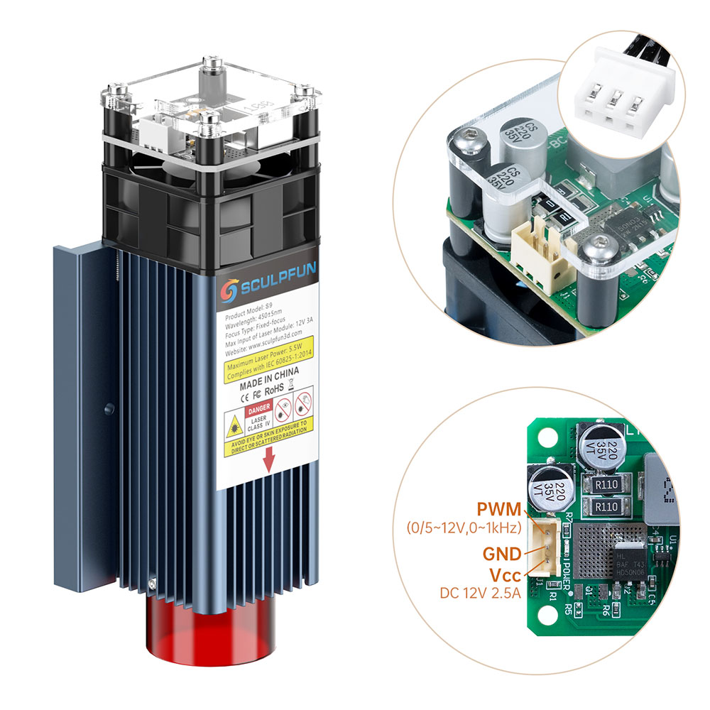
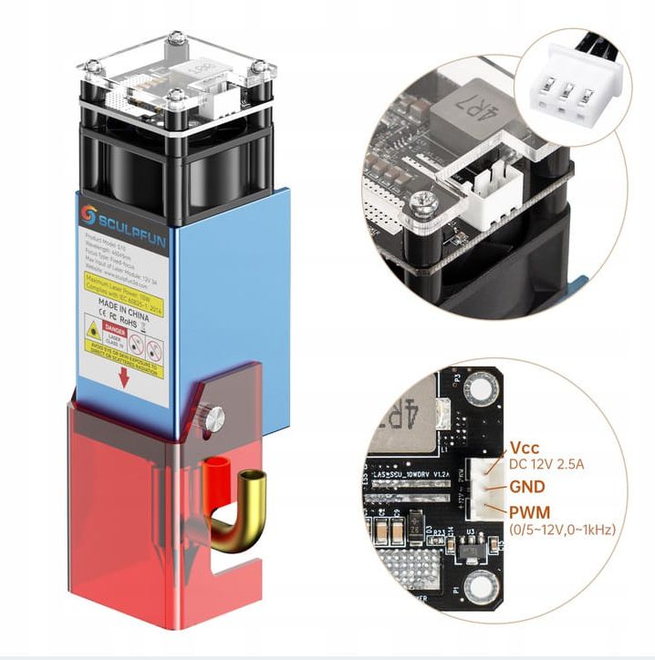
- Connection for 12V laser module (power supply), 2-pin, JST-XH 2.54
- Connection for PWM/TTL signal for the laser module, 1-pin, but designed on a two-pin connector, JST-XH 2.54
More components do not need to be connected. If you want to be a bit more flexible, you should also use connections for limit switches, relays, and fans if necessary. You can already see from the requirements that the components can also be operated with most mainboards from the 3D printing sector. This is also possible without any problems. However, according to my current experience, this is rather a niche, so I won’t go into it further here. However, I can add relevant sections if someone wants to share their experiences.
Overview Platforms
8-bit controller
Specifications
ATMega328P Processor
– AVR CPU at up to 16 MHz
– 32KB Flash
– 2KB SRAM
– 1KB EEPROM
Peripherals
– 2x 8-bit Timer/Counter with a dedicated period register and compare channels
– 1x 16-bit Timer/Counter with a dedicated period register, input capture and compare channels
– 1x USART with fractional baud rate generator and start-of-frame detection
– 1x controller/peripheral Serial Peripheral Interface (SPI)
– 1x Dual mode controller/peripheral I2C
– 1x Analog Comparator (AC) with a scalable reference input
– Six PWM channels
Power
– 2.7-5.5 volts
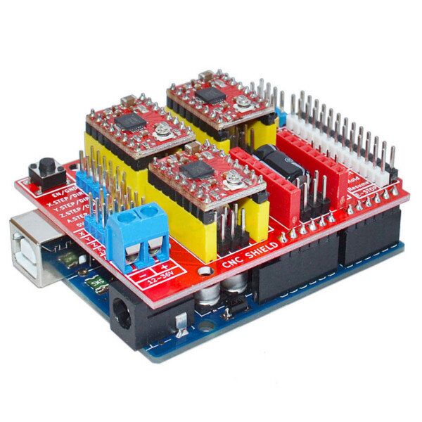
Examples of boards

32-bit controller
Specifications
ESP32 Processor:
– CPU: Xtensa dual-core (or single-core) 32-bit LX6 microprocessor, operating at 160 or 240 MHz and performing at up to 600 DMIPS
– Ultra low power (ULP) co-processor
Memory: 320 KiB RAM, 448 KiB ROM
Wireless connectivity:
– Wi-Fi: 802.11 b/g/n
– Bluetooth: v4.2 BR/EDR and BLE
Peripheral interfaces:
– 34 × programmable GPIOs
– 12-bit SAR ADC up to 18 channels
– 2 × 8-bit DACs
– 10 × touch sensors (capacitive sensing GPIOs)
– 4 × SPI
– 2 × I²S interfaces
– 2 × I²C interfaces
– 3 × UART
– SD/SDIO/CE-ATA/MMC/eMMC host controller
– SDIO/SPI slave controller
– Ethernet MAC interface with dedicated DMA
– CAN bus 2.0
– Infrared remote controller (TX/RX, up to 8 channels)
– Motor PWM
– LED PWM (up to 16 channels)
– Hall effect sensor
– Ultra low power analog pre-amplifier
Examples of boards

Firmware
For the 8-bit controllers, there is basically only one firmware: grbl. For the 32-bit controllers, there are now several projects that have ported the grbl firmware and developed some code around it. There is also the possibility to use the Marlin firmware known from 3D printing.
[Anyone who knows or has any other firmware to add, feel free to let me know!]
| FluidNC | Object-oriented hierarchical design Hardware abstraction for machine functions such as spindles, motors, and stepper drivers Extensible – Adding new features is much easier for both firmware and G-code transmitters. Open source. |
| grblHAL | GRBL consists of two parts: one that contains all the processor-dependent code — a hardware abstraction layer (HAL) — and one that doesn’t — the GRBL core. The HAL contains code that initializes the processor, knows about timers, PWM hardware, ports, pin addresses, communication, etc. The GRBL core only interacts with the HAL. Open source. |
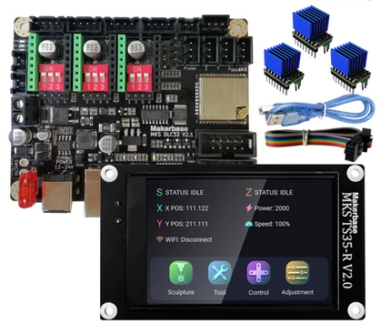
| MKS Firmware | The firmware is part of the MKS DLC32 motherboard kit, an offline engraving master control kit designed for desktop engraving machines. The hardware is equipped with a 32-bit high-speed ESP32 module and integrated Wi-Fi function and directly controls a 3.5-inch touch color screen; it can produce fast engravings and features a web interface. Closed Source. Update Oct. 2022: The firmware seems to be released open source here: https://github.com/makerbase-mks/MKS-DLC32-FIRMWARE |
Basically, it can be said that grbl runs on all 8-bit platforms (i.e., variants of the original Arduino UNO design). FluidNC and the MKS firmware usually run on most platforms based on an ESP32 chip. grblHAL is the most versatile firmware and can be used on various controllers (ESP32, STM32, SAMD21 and many more).
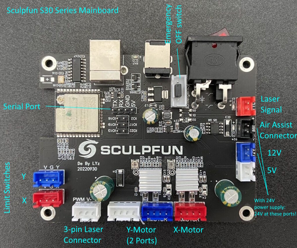
Connecting other boards
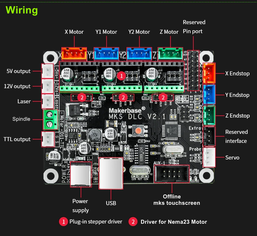
In the basic configuration, there are only four connectors or three logical connections that the S6/S9/S10 laser requires. Two JST-XH 4-pin connectors for the x- and y-axis motors. The laser module is connected on the original board with two connectors, a two-pole JST-XH connector for the voltage of the laser module and a two-pole JST-XH connector (where only one pin is occupied) for the PWM signal of the laser module. The motor connectors are actually identical on every board and can be connected directly. If the axes are twisted afterwards, this can be corrected in the firmware by a small setting. There are sometimes differences with the laser module, as some boards offer a three-pole connector. Here the plug must be changed or the cable replaced.

Stepper Motor Driver
Before we go to the motherboards, here is a short trip to stepper motor drivers. A nice explanation of what this is and why they are necessary is here: https://learn.adafruit.com/all-about-stepper-motors. In contrast to the Sculpfun motherboards, many other boards (especially the MKS boards presented here) do not have the driver chips for the stepper motors soldered on the board, but must be retrofitted. This has the advantage that you can choose between different drivers with different advantages and disadvantages. But you also have to keep in mind that you order these drivers; otherwise the board is not usable.
An overview of different types of stepper motor drivers is here, for example: https://all3dp.com/2/best-stepper-motor-driver/. The most well-known drivers are A4988 (usually the cheapest variant), DRV8825 (similar to the A4988) and the family of TMC drivers. Among other things, the TMC2208 and 2209 are popular there, but have now also been replaced by newer models. The advantages of TMC drivers are that the motors are much quieter, due to an improved sine wave in the control. In addition, some models can measure the motor current and thus detect whether the edge of the working range has been reached without a limit switch (sensorless homing). Since from my point of view the volume of the laser engravers hardly plays a role (since the laser fan is many times louder) and the function of sensorless homing is hardly supported, there is nothing against using the cheapest A4988 drivers, I think. TMC drivers are, in my opinion, exaggerated here. If you still want to use them, you can do that, I also think that the support for their features will be improved in the future.
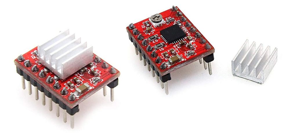
It is also important to make sure that the drivers are inserted the right way around on the mainboard! Otherwise, the mainboard and / or the driver will usually be irreparably damaged! All driver modules have a pin in one corner labeled “EN” (enable). The mainboards also have this label, or at least in the documentation. The EN pin must be connected to the EN socket!


I collected some settings of the microsteps for different stepper drivers. Check for your setup, what’s the best setting. This also holds for the Vref calculation.

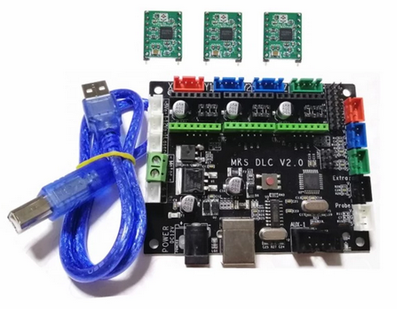
Makerbase MKS DLC (8-bit)
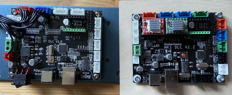
Since the technical data and layouts of the MKS boards are available open source, many other boards are based on these designs (including the Sculpfun boards). The advantage of these boards is the large number of connections and an overall successful electrical design. There are also suitable displays from MKS, with which you can even operate the laser offline.
The conversion is very simple. The board is identical to the Sculpfun motherboard of the S6 and S9 lasers, both in terms of mounting holes and connectors.
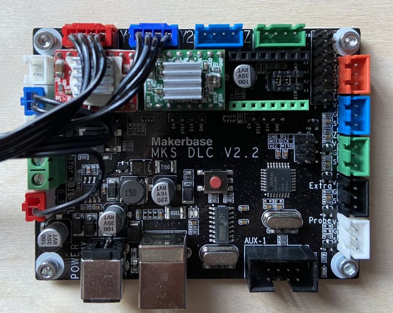
In the following picture, the MKS board is connected. Note: a stepper motor driver (in this case A4988) is used for the X and Y motors. Otherwise, the engines would not turn! The MKS motherboard can be operated with 12 or 24 volt voltage. Since the laser modules from Sculpfun only tolerate 12V, the 24V voltage must not be used!

Firmware
As firmware, the MKS board uses the standard firmware grbl, I recommend my version with optimized parameters for the Sculpfun lasers, see article Firmware update.
MKS DLC with display
The MKS-DLC motherboard offers an AUX port to which an MKS-TFT24 screen can be connected. However, this screen is not controlled by the motherboard, but represents its own control computer, which communicates with the motherboard via serial interface. You can save Gcode files to the SD card of the screen and have them lasered from there without a connected computer. However, only either screen or computer works, as both use the same interface. See also article on remote use of the laser.
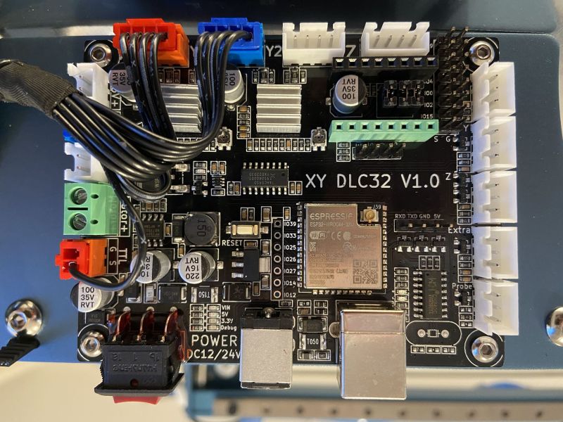
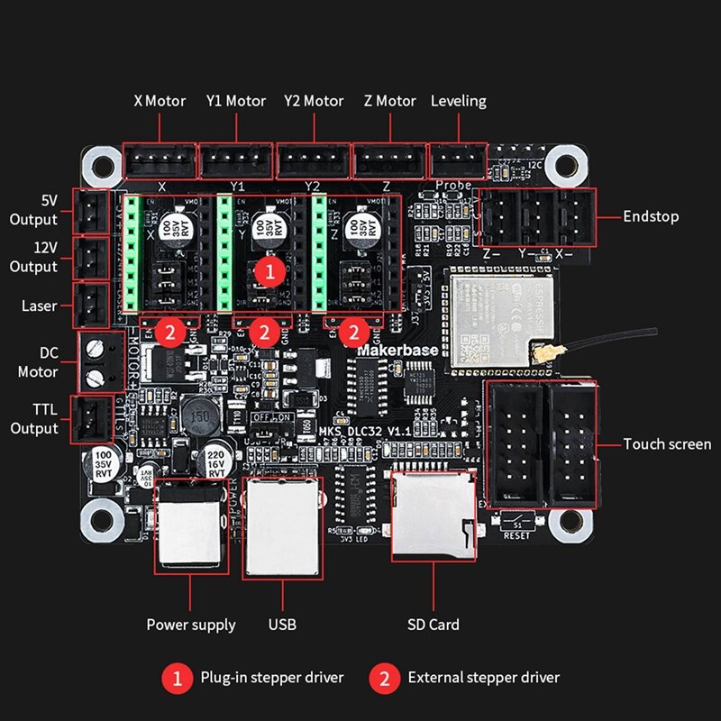
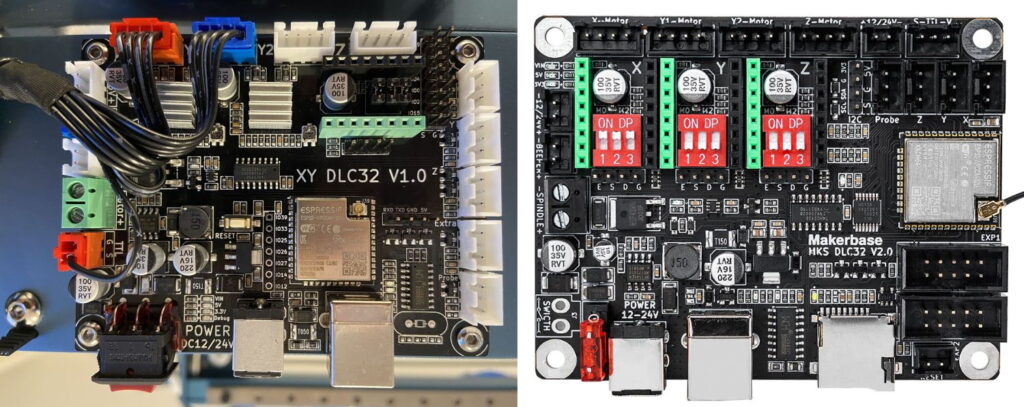
Makerbase MKS DLC32
The MKS-DLC32 uses the ESP32 microcontroller to control the laser. The benefits have already been mentioned above. Currently, a disadvantage is the rather low open-source firmware support, which will probably improve significantly in the near future. In contrast to the 8-bit board, the layout of the two boards is slightly different, but still offers all the necessary functions. The layout of the Sculpfun board is adapted to the 8-bit boards and can therefore replace old boards even more easily. The MKS board has a different connector for the laser, and therefore the cables need to be (slightly) adjusted.
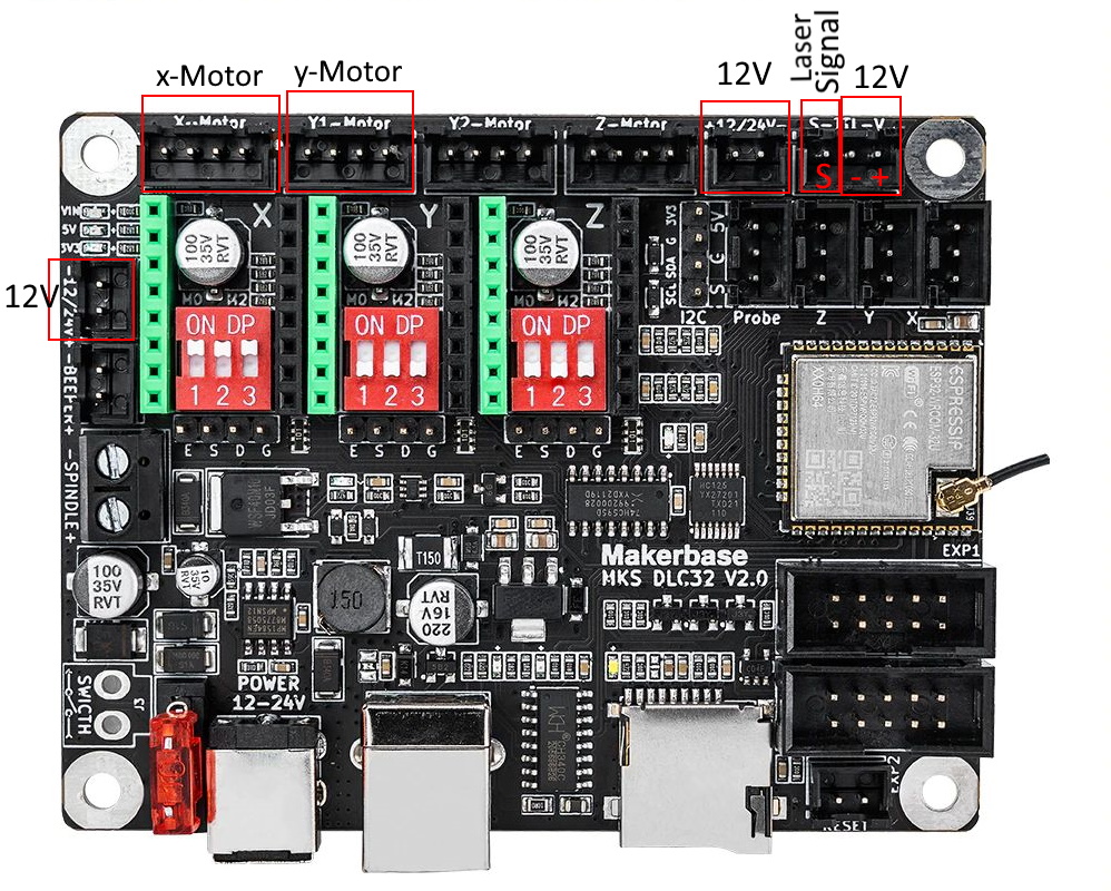
Connections
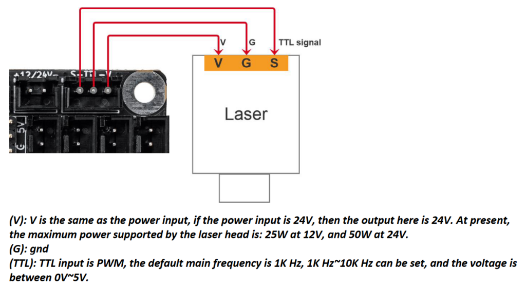
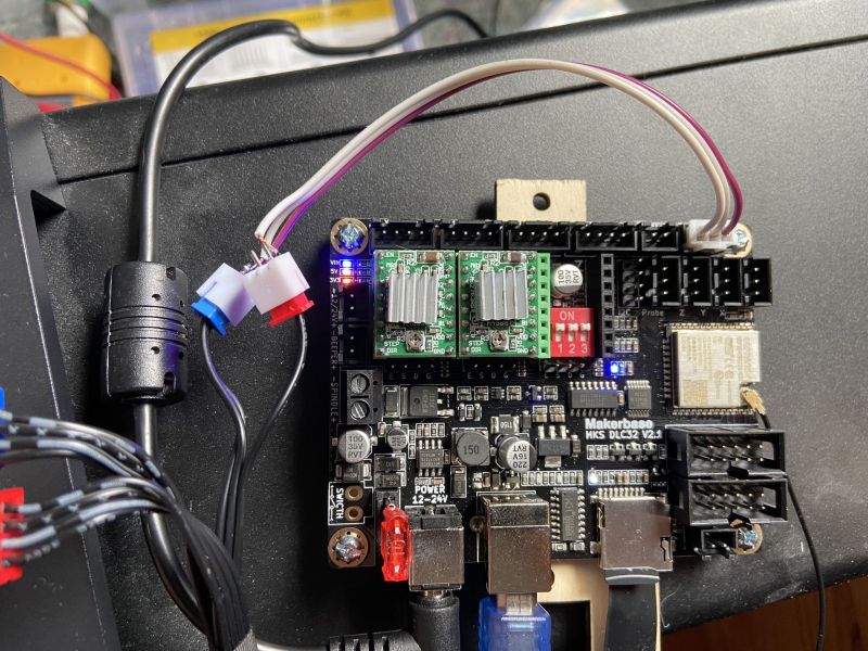
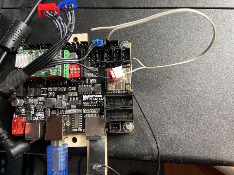
The plugs for the motors fit directly on this board as usual. However, the connectors for the laser module no longer fit completely. The power supply of the module can be taken from three ports, the laser signal is on one pin. Again, stepper motor drivers must be installed, otherwise the motors will not move! The MKS board can be operated with 12 or 24V, but since the voltage is passed through to the laser module, Sculpfun lasers may only be operated with 12 volts!
I tested two set-ups, both to use all signals from the designated port, and to keep the 12V plug and only get the signal from the TTL socket. Both are possible. You can do this as you like, depending on whether you want a clean solution or a little more tinkering.
Firmware
Since the two boards are basically compatible, the firmware can also be [However, I have not yet been able to test all the details to see if there might be incompatibilities] replaced theoretically. The Sculpfun firmware can be flashed to the DLC32 board and vice versa. However, the DLC32 still offers the possibility to connect a display, which only works with the original firmware. All Firmwares emulate the standard serial connection interface, so they are compatible to LaserGRBL, LightBurn etc. Though, they might not be detected correctly. If you have a choice, select “grbl” as type of laser/firmware.
Sculpfun Firmware
The firmware for the Sculpfun S10 can easily be installed on the DLC32 board. This is described in the chapter Firmware Update. This runs the board and the settings are made according to the Sculpfun specifications.
MKS Firmware (+ Display)
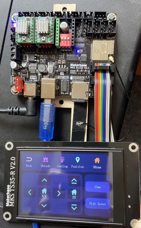
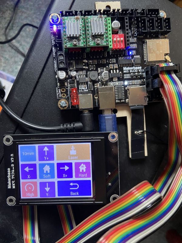
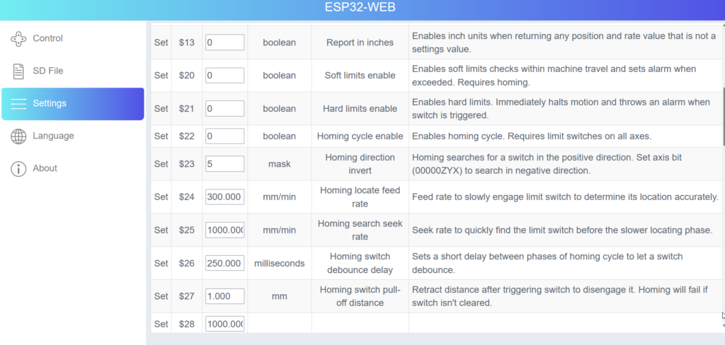
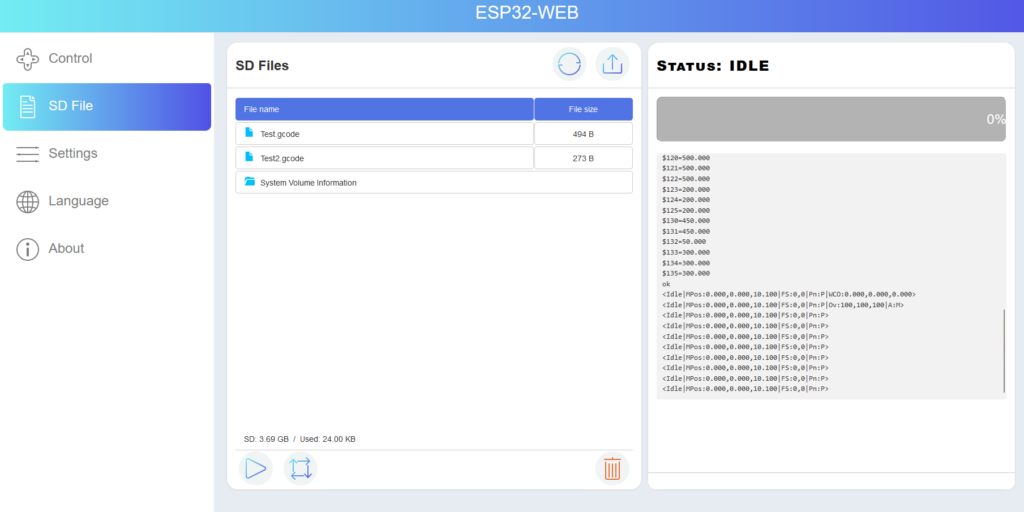
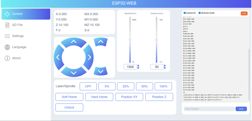
The MKS firmware is of course even better adapted to the board. Among other things, you can use the touch display module and a web interface. You can download the firmware here: https://github.com/makerbase-mks/MKS-DLC32/tree/main/firmware. You can also flash them with the tool for the Sculpfun board, as described here: Firmware update. Attention: there is a 2.4-inch and a 3.5-inch display. A different firmware is required here! At the time of writing, there was version 2.08 for the 2.4″ display and version 2.10 for the 3.5″ display. So, the latter seems to be developed a little more actively. The menus and the menu navigation are also very different from each other. Here are a few pictures of the display and the web interface:
“Deemoss” created a housing for the MKS Board and the TS35 display: https://www.thingiverse.com/thing:5711454


Another design that you can produce using your laser is provided by Patrick: Download LightBurn file. It looks like this:

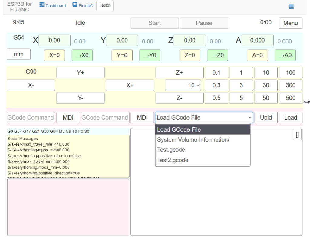
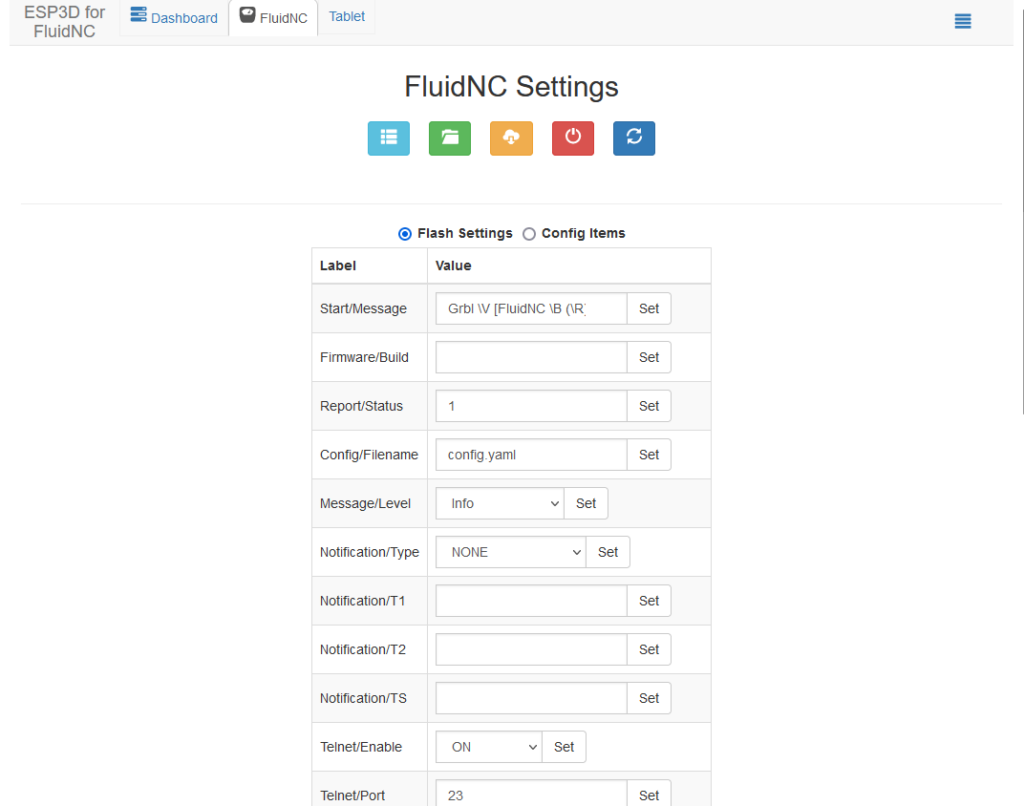
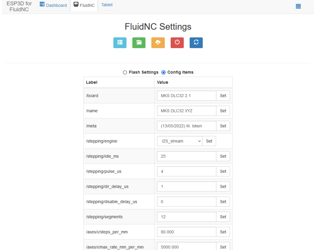
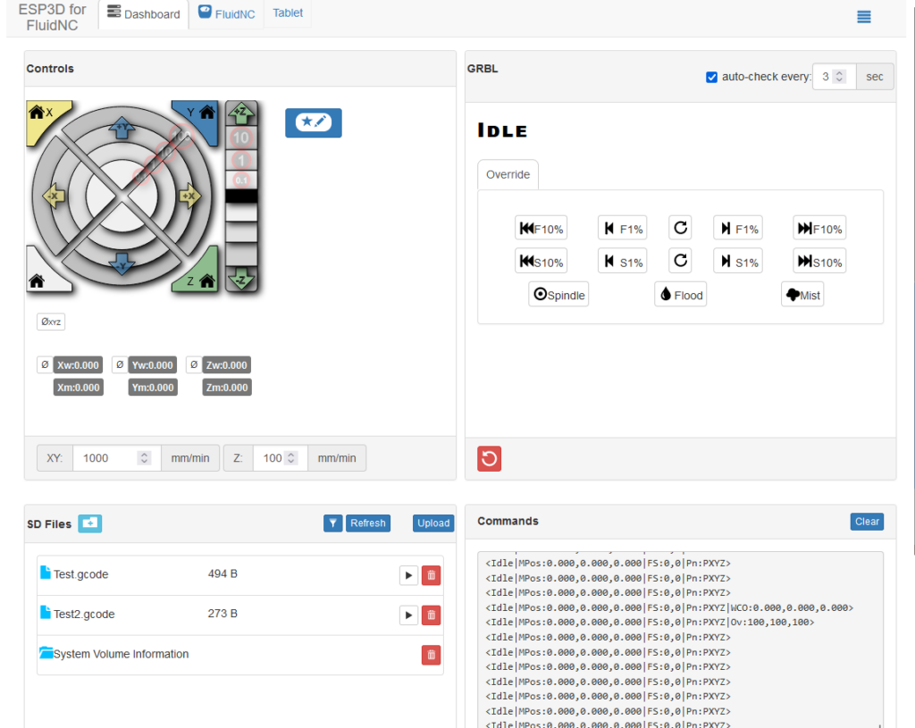
FluidNC
The FluidNC firmware can be downloaded here: https://github.com/bdring/FluidNC. For the S9 I also created a working configuration, see firmware page. This should also work with the S10, but I have not yet tested. The installation works with a script that is included in the installation archive. You do not need the MKS tool, as with the above variants. There is probably work on display support, currently there is none. The control takes place via the web interface (or LaserGRBL/LightBurn etc.).
Update
There is now also a version of the FluidNC config file for the S30 mainboard: firmware page
Since the MKS firmware is currently not very actively developed and only fitting for the MKS mainboard, I think that FluidNC has the greatest potential to become the successor of grbl for the 8bit boards.