A question that arises very often is whether you always need a computer to control the laser. At first glance, this seems very impractical and also has some disadvantages. In fact, the laser does not necessarily have to be connected to a large control computer. There are a few ways to do the whole thing remotely, so to speak. These possibilities are presented here.
Warning
Basically, the laser should NEVER (not even for one minute) be operated without supervision!!! Therefore, these instructions are only there to help in case of difficult technical conditions, but you should NEVER EVER operate a laser remotely and without direct supervision. A few examples of burned down lasers can be found here.
Sculpfun S10/S30 series with Bluetooth functionality
Note S30 Ultra: the S30 Ultra series is already fully equipped to use the Bluetooth functionality. It is also already enabled in the firmware. Just use Windows settings to search for new Bluetooth devices, connect to the “Sculpfun” device, and you’ll get another COM port that is using the serial connection. In LightBurn or LaserGRBL, connecting to this new COM port will establish the Bluetooth connection.
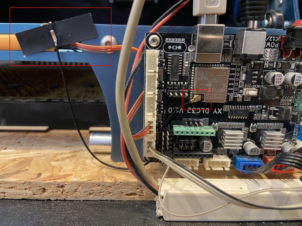
The Sculpfun S30 series has a motherboard with the ESP32 processor, which already includes the Bluetooth functionality. The first official firmware update has just been released, with which the function can also be activated. See the firmware page for download. For it to work stably, an antenna must still be attached to the module. Specifications of the antenna: IPEX 1 WIFI/BT 4DB.

The S30 Bluetooth function can then be switched on in the console with the command “$Radio/Mode=BT”. Bluetooth must also be active on the host PC. You can now search for a new Bluetooth device (“Sculpfun”) and pair it. Afterward, a new COM port should appear in the device manager, which uses the Bluetooth connection. You can then select this COM port in LaserGRBL or LightBurn for the connection.
The S10-firmware has also been updated to support Bluetooth connections (see firmware page). You need to add an antenna as well. The Bluetooth function is active there immediately. You have to search for a new Bluetooth device, it should be called “btgrblesp”. Pair with it and then select the new COM port that pops up in device manager. You can only use either Bluetooth or USB, not both! The USB cable must be disconnected, to connect successfully.
Bluetooth module for remote serial connection
Note
Wireless connections are usually not very stable. I would advise against using such solutions in productive operation. If the connection briefly breaks off, the current project is probably destroyed.
Another note: the serial pins and the USB connection use the same physical connection to the microcontroller. It is not possible to use both USB and Bluetooth at the same time! You need to physically disconnect the other connector.
The easiest way to remove the wired connection is to replace it directly with a wireless connection. The HC-05 and HC-06 Bluetooth modules are particularly suitable for this and very cheap (around $5). These modules use the SPP (Serial Port Profile) to transmit a serial connection via Bluetooth. Here you can find an excellent manual about these modules and their programming. Otherwise, you can just search for “hc-06 arduino” and find thousands of projects. I had a HC-05 module available and used that, but with the HC-06 it works nearly the same.
Preparation: configure module
First, the module must be configured correctly so that it can later talk to the laser mainboard. The default setting of the serial interface is 9600 baud/s and the interface on the laser uses 115200 bps. This must be set accordingly. This can be done either by so-called AT commands, or by a small tool, both can be found in this excellent manual: https://wolles-elektronikkiste.de/en/hc-05-and-hc-06-bluetooth-modules. I had a USB-BUB-II adapter in my tinkering box (similar to this), which I could use to make these settings easily. To achieve this, simply connected the adapter and then used the tool linked in the instructions above to change the configuration. This already completes the preparation.


Connection cable
As stated everywhere in the examples for the HC-05/06, the serial connection only tolerates 3.3V. Since the laser mainboard works with 5V, a level conversion must be done. The easiest way and recommended in most manuals is a simple voltage divider with 1kOhm and 2kOhm resistors. So that they don’t fly around wildly, I integrated them into the cable for the module.


Connection to mainboard
The connector for the mainboard has the pinout VCC-GND-TXD-RXD. This connector then fits on the MKS-DLC board and all Sculpfun mainboards, except the first S6 series.


Using Windows, you only have to pair with the Bluetooth module (default pin is 1234) and you are done. Windows creates a new COM port for the module. As soon as this port is selected in LightBurn, Windows establishes the connection and the laser can be controlled as usual. As already mentioned, I would not expect the transmission quality to be as reliable as via cable.
Create G-code
The prerequisite for all “remote controls” is that the project to be lasered is available as a G-code file. Both LightBurn and LaserGRBL can export this G-code. With LaserGRBL, this can be done in the menu “File” and then “Quick Save” or “Save (Advanced Options)”. LightBurn has the “Save GCode” option in the Laser window.


OctoPrint
For anyone who comes from the 3D printing sector, OctoPrint is a common name. It is one of the most widely used tools to remotely manage a 3D printer. In fact, OctoPrint is also able to control grbl lasers. For this there is the plug-in “Better Grbl Support”.
Installation
OctoPrint is designed to be installed on a Raspberry Pi single-board computer. This makes the installation very easy. The Pi is connected to the laser via USB and can then control the laser via a web interface. I tested it with a Pi 3, but actually a Pi Zero (W) should be enough. The software and installation instructions can be found at https://octoprint.org/. Then go to the settings of OctoPrint and install the plug-in “Better Grbl Support”. The plug-in makes some settings and is then ready for use. If you have a webcam connected to the Pi, you can also see the picture of it.

In this window you now have the possibility to upload G-code files and have them lasered. I did some tests that also worked perfectly.
Display with control option
If you have no problem with replacing your motherboard, then you can also install an offline control option here. You can get additional information about the mainboards here.
Note
I just received the information that nearly all Sculpfun mainboards (also with version 1.0 printed on them) feature the extension port to attach a display. Not only the 1.1 version. Just check if there are four pins labeled RXD, TXD, GND, 5V. Then you can attach the MKS-TFT displays as well.
The latest version of the MKS-DLC Controller Board, V2.1 includes an AUX port to which a screen can be connected that takes control. Especially at AliExpress you will find many offers.


There is also a related board, the MKS-DLC32. Here, an ESP32 chip is used, which is much more powerful than the 8bit Atmega controllers. This enables new functions and improved control algorithms. The original grbl firmware is not offered for this controller. It doesn’t seem to be really developed any further anyway. Therefore, there is a new project for this: FluidCNC. The firmware is mostly compatible with grbl, but also differs in some areas. Therefore, you have to deal with it a little more closely. See this article for more information.

Display Tests
A few of the ordered displays have arrived. What I didn’t realize before is that there are two different types of displays from MKS. There are MKS TS24 and TS35 and MKS TFT24 and TFT35. And here is also a big difference. The TS displays are pure touchscreens, with no controller capabilities of their own. Similar to the 3D printer displays, they are connected with two connectors and can thus control the main board. The TFT displays are standalone displays with their own firmware that acts as a host. That is, they run independently and control the main board via the serial port, just like the normal control PC does. Therefore, you can actually connect them to almost any main board, which exposes the TX/RX ports of the controller and run G code files.
Therefore, only the TFT displays work with the MKS-DLC and the TS displays only with the MKS-DLC32. And those only work with the specially developed firmware, if you use the DLC32 with other firmware, then the displays no longer work.
Update new Sculpfun Mainboard paired with MKS TFT24
I have tested the TFT24 display with both the MKS DLC v.2.2 and the new Sculpfun main board XY DLC V 1.1. Both work wonderfully. With the Sculpfun main board, you only have to plug the connector the right way around, as there is no real port, only the four-pin header.
Note
As already stated above, I just received the information that nearly all Sculpfun mainboards (also with version 1.0 printed on them) feature the extension port to attach a display. Not only the 1.1 version. Just check if there are four pins labeled “RXD, TXD, GND, 5V”. Then you can attach the MKS-TFT displays as well.
The firmware of the display is as far as I have seen not open source and unfortunately only rudimentary implemented, some buttons do not work whatsoever; the speed cannot be set below 1000 mm/ min, and other bugs. But running a Gcode from the SD card works!


ESP3D
Another option to add WiFi-capabilities to 8bit-boards is ESP3D. You can find information about it here: http://esp3d.io/index.html. This works by using an ESP32 board like development boards or the ESP32-cam board to control the laser board via the UART interface. Basically, it is providing a web-based interface to upload gcode to ESP3D which can then be sent to the laser via UART and without any additional PC.
I did not have a very close look at it, it seems to be in a usable state, but still some work to be done, and the latest releases are about one year old. So, I can’t tell about the project’s status. In general, a Raspberry Pi running OctoPrint would be very similar and much more powerful than this solution. Though, a nice idea.
