RTFM
A LOT of questions that are asked about the software controls are already explained in the respective software documentation materials. I STRONGLY recommend taking the time and go through, you will get a lot of useful information and hints for your daily work. For LaserGRBL you find it here. LightBurn provides an online documentation and PDF version of its documentation. The LB PDF is about 240 pages, but don’t be afraid, I read it in one evening (not every single page is relevant). For example, did you know that it does matter if you draw a selection rectangle on objects in LB, that it does matter if you do it from left or from right? That function is GENIUS!
If you prefer watching, here is a video from LightBurn on how to set up a Sculpfun laser with LB.
Download sources
- USB driver: https://sparks.gogo.co.nz/ch340.html (Windows & Mac, Linux usually does not need one) [there is an updated version for M1 Macs here: https://github.com/WCHSoftGroup/ch34xser_macos] or google for “ch340 driver”, or use the driver included in LaserGRBL (Windows). I received some other versions of the driver that might be worth to test if you have issues with the drivers above (direct downloads): Driver Win, Driver Mac, Driver with baud rate compensation (Win).
- LaserGRBL: https://lasergrbl.com/download/
- LightBurn: https://lightburnsoftware.com/pages/trial-version-try-before-you-buy The trial version can be used for free for 30 days. If you want to buy the full license afterwards, choose the “LightBurn Software – GCode License Key” variant. It’s around $60 for a lifetime license, with updates for one year. Note: never use pirated versions of LightBurn! First, its price is really low compared to the functionality offered; but more important: pirated versions of LightBurn will behave unpredictable (creating weird movements or messages). These are no errors of the setup or system – it’s just illegal use.
Basic setup – add laser
USB Driver
First install: Software / drivers
The control boards usually use a CH340 USB driver chip, whose driver is not shipped with most operating systems. You can either google and download the driver yourself, or you can install LaserGRBL, which provides you with an option to install this driver for you. Since we use that tool later, it makes sense to install it anyway. https://lasergrbl.com/
Procedure installing USB driver using LaserGRBL
Of course, first you need to install LaserGRBL. Then, start it.
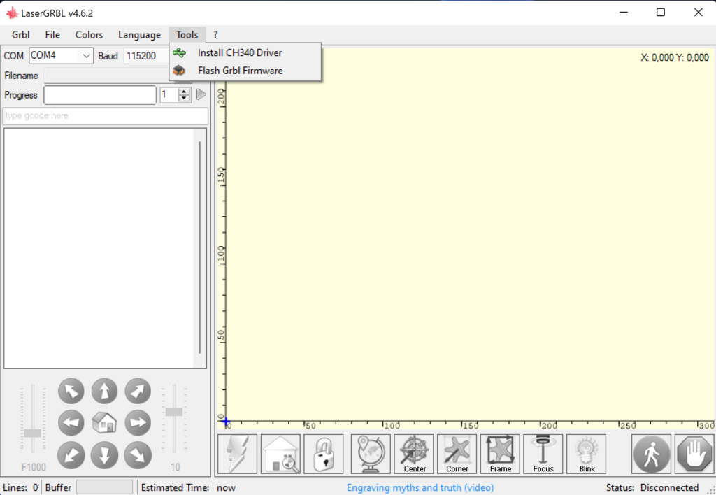
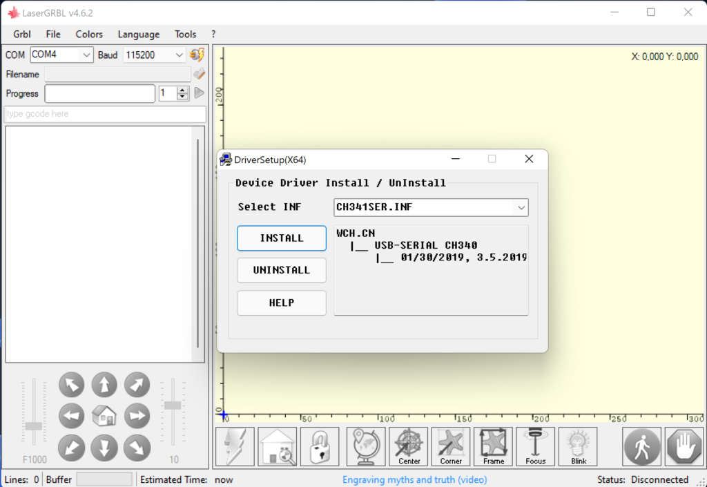
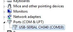
After installing, you might need to unplug and re-plug your laser to your PC. Finally, check your device manager if the device is present (and note the number of the COM port assigned, you will need that soon):
Procedure installing USB driver macOS
For macOS operating systems, I recommend downloading the driver here https://github.com/adrianmihalko/ch340g-ch34g-ch34x-mac-os-x-driver. I used the version CH34x_Install_V1.5.pkg (macOS 10.15.5)
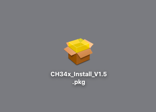
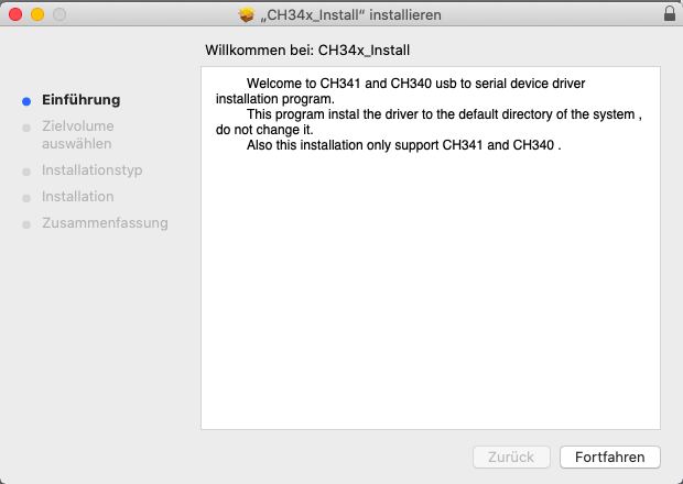
After installation, the system must be restarted. The laser can then be plugged in. If you are familiar with the terminal, you can use the command “ls /dev/tty.*” to see if devices with tty.usbserial-XXX or tty.wchusbserial-XXX in their name are recognized. This should be the laser.

Finally, LightBurn can be installed.
Procedure of installing in Ubuntu 22
According to some sources (e.g. LightBurn Forum), the setup in newer Ubuntu versions is slightly more complicated. Follow these steps to get it running:
Check with “lsusb” if the laser (or the controller, of course) is displayed. There should be an entry “1a86:7523 QinHeng Electronics”.
lsusb
With admin rights, go to the folder: /usr/lib/udev/rules.d/ and search the file “85-brltty.rules” and open it with a text editor like nano.
sudo nano /usr/lib/udev/rules.d/85-brltty.rulesThere should be a line that can be found quickly by searching for “1a86”: “ENV{PRODUCT}==”1a86/7523/*”, ENV{BRLTTY_BRAILLE_DRIVER}=”bm”, GOTO=”brltty_usb_run””. Put a “#” at the beginning of the line to make it inactive and save the file.
# ENV{PRODUCT}=="1a86/7523/*", ENV{BRLTTY_BRAILLE_DRIVER}="bm", GOTO="brltty_usb_run"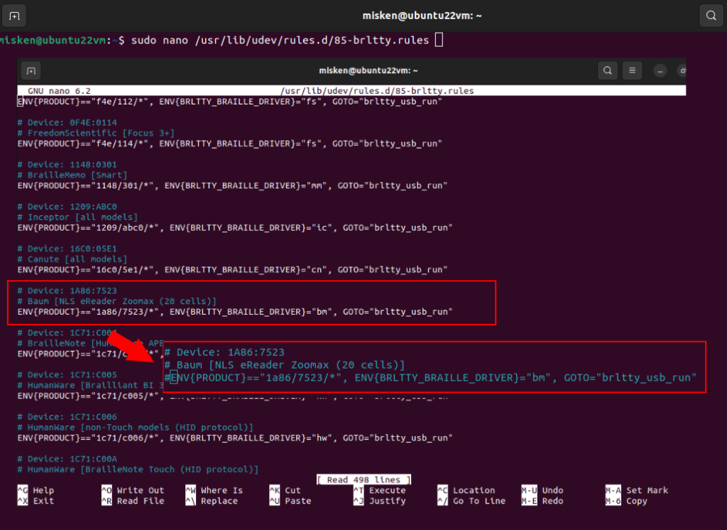
In the same folder there is also the file “70-uaccess.rules” which you also open with admin rights in the text editor and add the following entry at the very bottom after “3D printers, CNC machines, laser cutters, 3D scanners, etc.”: “SUBSYSTEM==”tty”, ATTRS{idVendor}==”1a86”, ATTRS{idProduct}==”7523”, GROUP=”users”, MODE=”0666””. ATTENTION: At the end of the file it says “LABEL=”uaccess_end”” and that must be the last entry. So, the newly added line must be copied in above it.
sudo nano /usr/lib/udev/rules.d/70-uaccess.rules

SUBSYSTEM=="tty", ATTRS{idVendor}=="1a86", ATTRS{idProduct}=="7523", GROUP="users", MODE="0666"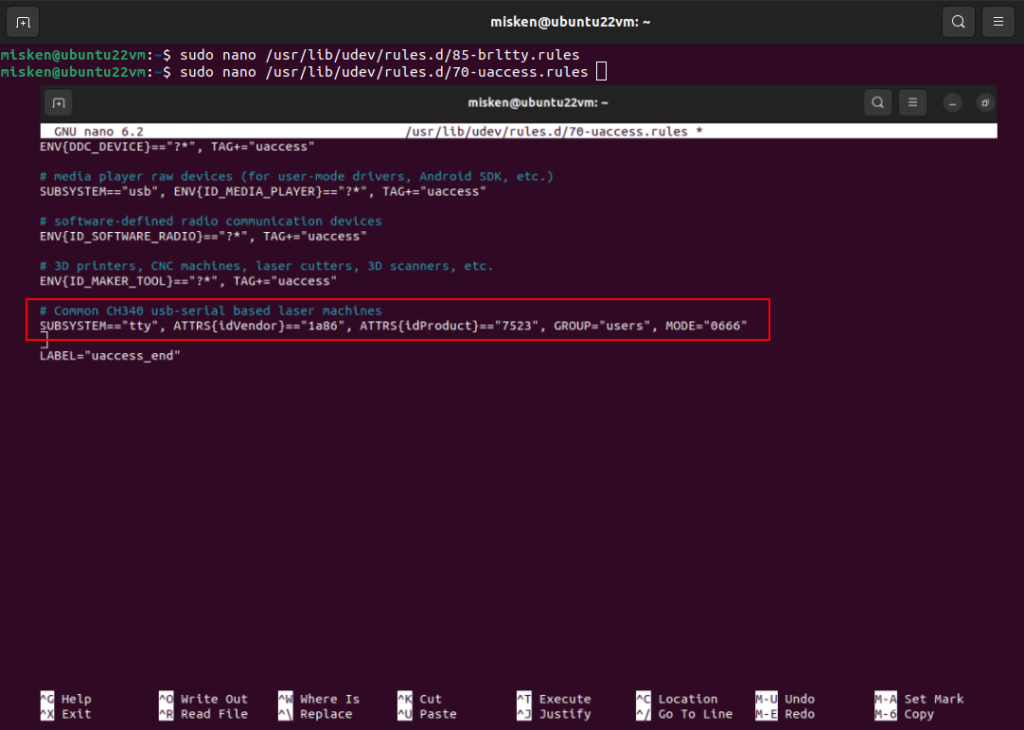
Restart and everything should work again. I created a video showing the complete process:
If those steps don’t fully work, you can additionally try to remove the brltty-package completely (thanks, Sebastian):
sudo apt-get purge --auto-remove brlttyThen reboot and check again if the USB device is now properly recognized.
If you use Windows 11 and there is no COM port list in device manager, you can try this tip: “To add a COM Port, you can launch Device Manager, highlight your Computer Name at the top of the list, select action menu and add legacy hardware. Follow the wizard to install the hardware that I manually select from a list, choose ports (COM & LPT), Standard and Communications Port.”
When the USB driver is installed and the firmware is updated and set correctly, we come to the second part of the control setup. A software on the control PC must generate the mentioned G-codes and send them to the microcontroller. Especially popular are LightBurn and LaserGRBL. LaserWeb is another tool.
LaserGRBL
In LaserGRBL, you don’t need to configure your laser in terms of model and type, since it only supports grbl-based lasers. Just select your correct COM port and click on “Connect”.
Step-by-step instructions
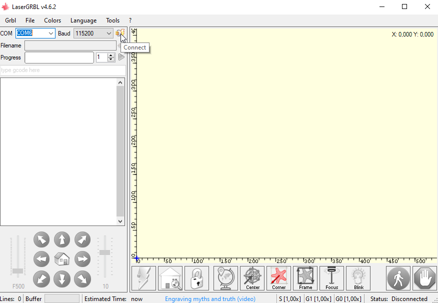
In the console window, you should get a message displaying the version of your grbl firmware if connected successfully.
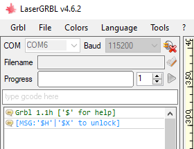
You can now start to command your laser. For details about the usage of LaserGRBL, refer to the online help or documentation.
LightBurn
Since LightBurn supports different types of laser controllers, you need to provide a little more information about the laser.
Notice
Automatic device detection (“find my laser”) usually does not work very well with Sculpfun lasers. You should add them manually. This holds especially for LightBurn on MacOS and the S10 device!
See the step-by-step instructions below (the S10-S30 models procedure is the same as S6/S9).
Procedure using import of provided device profile
I have created a profile for the S10 and S30 Pro Max that can be imported directly into LightBurn. This eliminates the need for the steps below. The profiles can be downloaded here: S10 Device Profile, S30 Pro Max Device Profile. In LightBurn, these profiles can be imported via the import button:
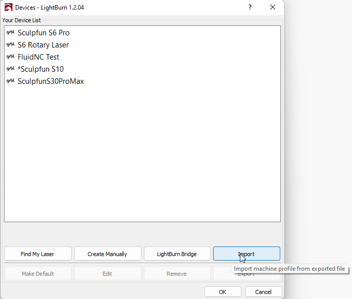
You still need to select the correct COM / connection port to communicate with the laser.
Step-by-step instructions Windows
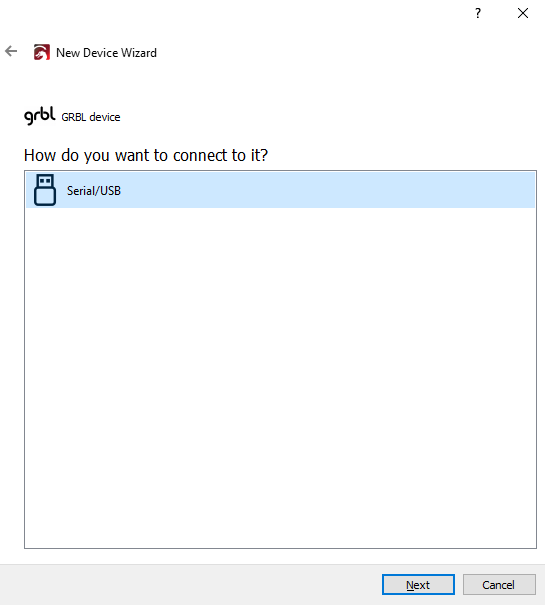
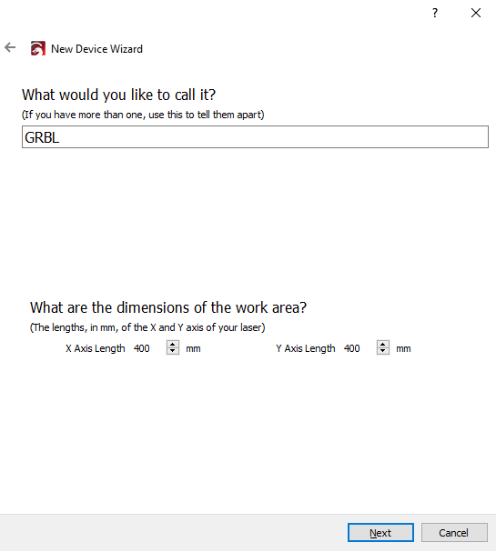
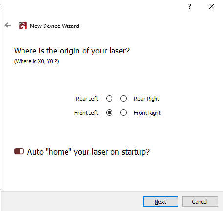
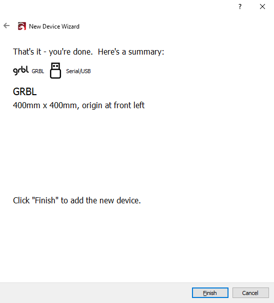
Start LightBurn. On first startup, it might ask you about to configure a new laser right away. Then you can omit step 1.
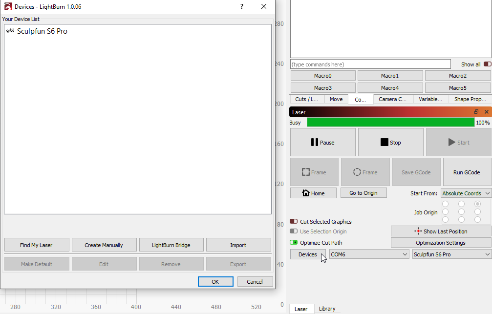
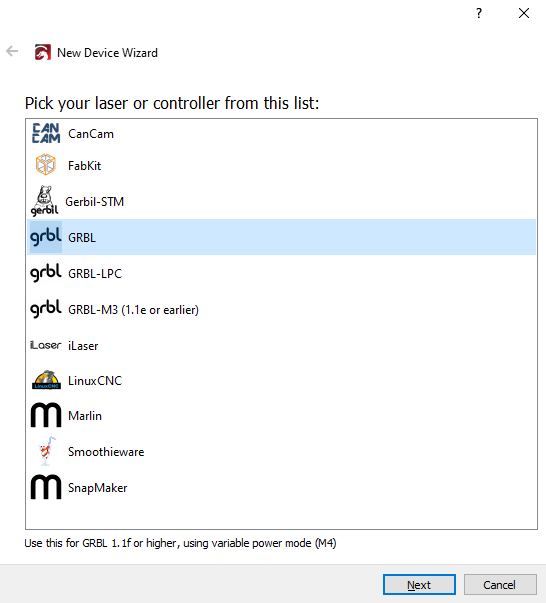
If you did not flash your firmware, you might have a version below 1.1f. Then you need to select GRBL-M3. Autodetection from LightBurn does not always work, in my case I had the latest firmware version and LB still detected GRBL-M3. You then must change it manually.

Supplement macOS
For macOS, the setup is quite analogous to Windows. Find my laser did not work for me, I had to select “create manually”.
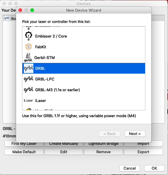
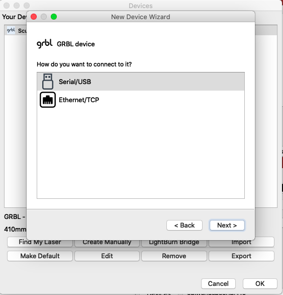
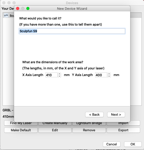
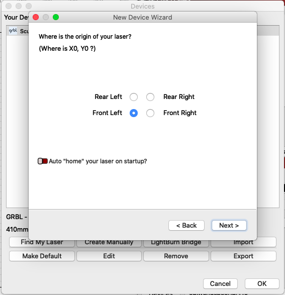
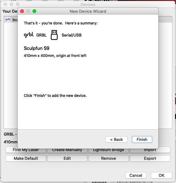
When the laser is created, the laser should now be selected in the laser window and the interface selected in the USB driver installation section should be selected. If you do not find a suitable interface here, the driver is not installed correctly.
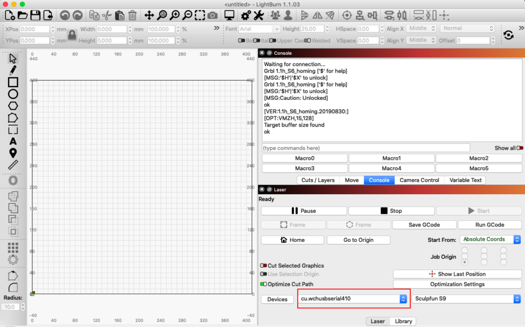
Meanwhile, LightBurn released complete installation videos for S9 and S30:
LightBurn Settings
I recommend that you set the following settings in LightBurn.
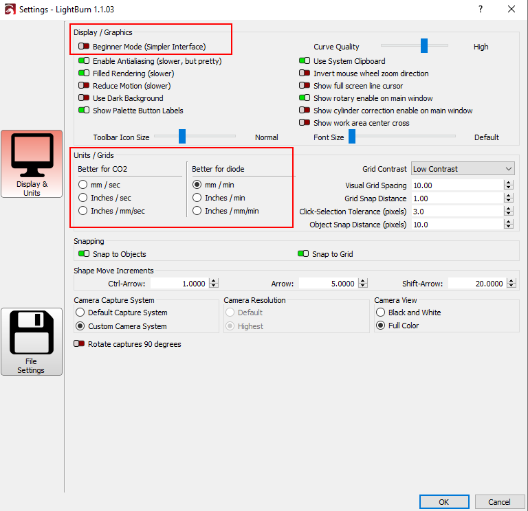
General settings: I would turn off “Beginner Mode” here, so you can see all the options as well. I think you will still not be overloaded, and it helps if you immediately find the options that others recommend. Essential: “Units / Grids” must be set to “Better for diode“! Otherwise, the speeds will not fit!
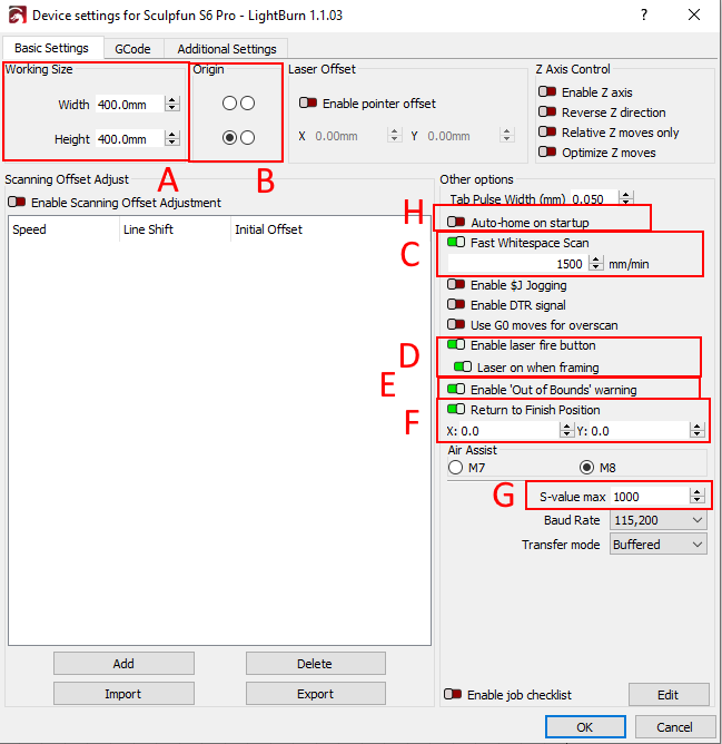
Device settings:
- A) Here the size of the working area is entered.
- B) Here the origin is selected, which is used to calculate coordinates. This should be entered as bottom-left.
- C) Fast Whitespace Scan describes the speed with which the scan is performed over empty space. For example, if you laser two objects with space between them, the laser will continue between the two objects with the layer settings. But often you can quickly skip the area and save a lot of time.
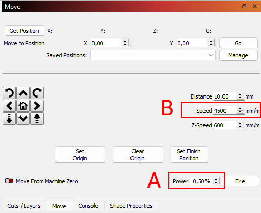
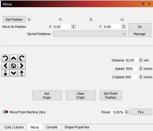
- D) You should activate the Laser Fire button and also turn on the second switch so that when you “frame” the object, you can see the laser point on the work surface and align your workpiece to it. You need to set some (low) percentage in the Move-window next to the fire button; otherwise it doesn’t fire at all. Stay as low as possible; otherwise, you will already mark the material while framing.
- E) You should only select this setting if you have set up limit switches and homing. Otherwise, this will result in many false alarms.
- F) If you always want to return to the same position after a job, you can enter this here. This only makes sense if you use absolute coordinates (system with limit switches). Better do not put 0,0 here, use about 10,10 to stay away from the switches. This sometimes causes issues otherwise.
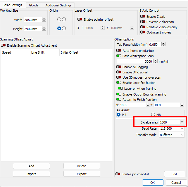
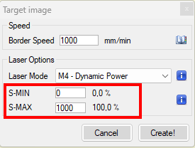
- G) The S-Value must be set to 1000, so that the laser can be operated with 100% power. 100% correspond to 1000. If you never want to operate the laser with more than 85%, for example, you can enter 850 here. Then no higher value is ever transmitted to the laser.
- H) If you have no homing switches, you should turn this setting off. Otherwise, you will get a warning that the homing procedure has failed at every reconnect (“Error 5: Homing cycle is not enabled in grbl settings”).
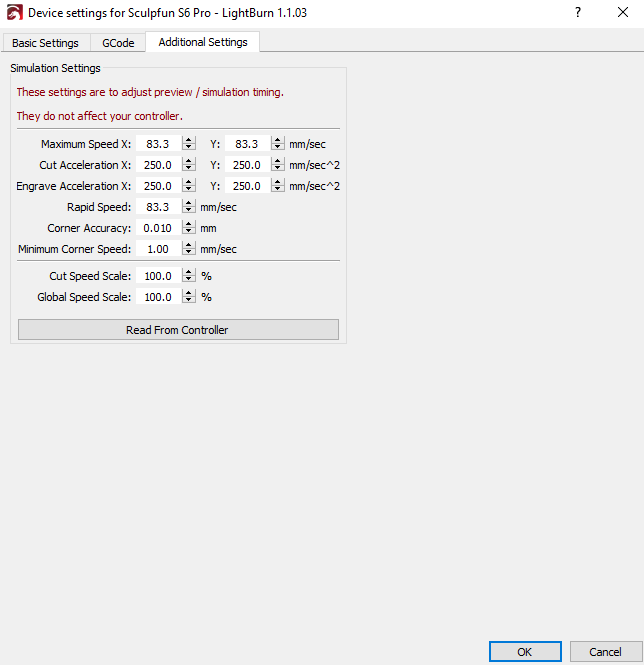
Additional device settings: click on the button to update the values with those from your firmware. Then the calculation of project duration in preview window is more exact.
Move Window:
- A) You need to set some (low) percentage in the Move-window next to the fire button; otherwise it doesn’t fire at all. Stay as low as possible; otherwise, you will already mark the material while framing.
- B) Set a travel speed that is used for all moves that do not have a specific speed set (like the move buttons, but also the automatic “return to finish position” functions and “set laser position” tools.
LightBurn usage
The team of LightBurn created a great video to get you started and show the initial settings and tools of it:
Error 5: Homing cycle is not enabled in grbl settings
Strictly speaking, this is not an error and does not affect the function of the laser. The message says that a command for automatic homing was sent to the laser, but this function is not activated in the laser at all. If you don’t have limit switches, just turn off “auto home at startup” (see above, option H). If you have limit switches (like with the S30 series), the switches are available but usually, the homing function is not enabled in the firmware. To change this, either send “$22=1″ in the console window or open the “machine settings” and enable “Homing cycle”. Be sure to click on “Write” after changing.
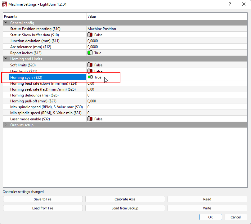
I also recommend doing some other tuning related to homing, you can read the full article here.
Alarm 8: Homing fail
If you get Alarm 8 “Homing fail. Cycle failed to clear limit switch when pulling off.”, in most cases it is because the limit switches have to be inverted. The firmware recognizes the switches as permanently pressed and therefore cannot start a homing cycle. In that case, parameter $5 must be changed to 1 (or back to 0 if it was 1). Then the error should disappear. See the article about limit switches for more details.
Workspace size / Alarm 2 and Alarm 3
Especially for the S30 series, but also for the other models without homing, you should make sure that the working range is set correctly. The firmware often has a default setting that is very optimistic. As a rule, this can hardly be achieved. Therefore, the new size of the working range should be set in the firmware so that the laser does not go beyond the limits. For this, the parameters $130 (x) and $131 (y) are needed. These values can be set in the console by the command “$130=380” (example, to set the length of the x-axis to 380 mm). Due to individual changes (e.g., hoses of an Air Assist) the value can also vary individually. It is best to test it out manually for your laser:
- Perform homing or start the laser with the head at the bottom left (so that the position at the bottom left is 0,0, see also coordinate systems).
- Now move the laser with the arrow keys (not manually!) to the possible limits (first you can make larger steps, e.g., 10 cm, at the end you move millimeter by millimeter). The values that are then displayed in the Move window are the maximum limits of your laser.
Here is a list of approximate sizes of the workspace:
| with limit switches | without limit switches | |
| S6-S10 | 385 x 390 | 400 x 410 (maybe) |
| S30 5W + 10W + Y Extension Kit +XY Extension Kit | 380 x 385 380 x 920 900 x 920 | — |
| S30 20W + Y Extension Kit +XY Extension Kit | 370 x 363 370 x 900 890 x 900 | — |
| S30 Ultra (no extension kit available) | 600×600 | – |
s-value / s-value max
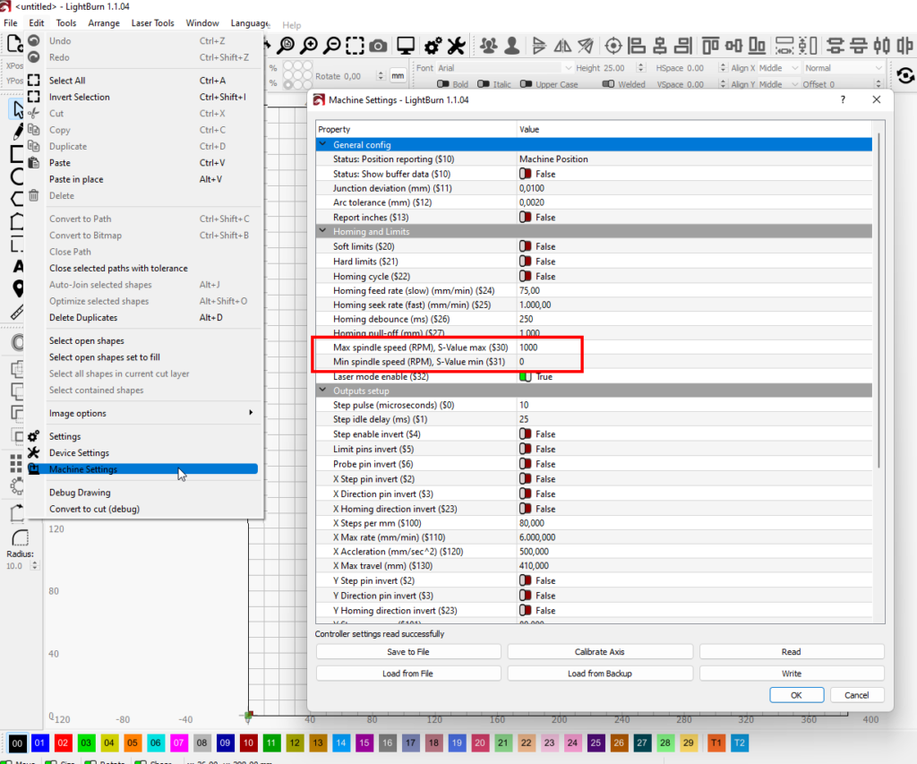
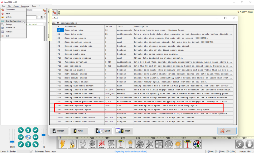
This often leads to incorrect assumptions or strange tips in forums, so here is a brief explanation. Laser modules are usually controlled with a PWM signal. This signal uses a duty cycle of 0 to 100%, which in analog terms results in a voltage value of 0V (=off) to 5V (=100% on). The firmware of the laser is based on grbl (see article in the introduction). Here there is the internal speed value (hence the S), which was originally used to control the speed of the spindle on CNC machines, but in the variant for lasers there is also the power value for the laser modules. In the firmware, the limits are defined with the value $30 (max spindle speed) and $31 (min spindle speed). In current grbl versions, the minimum value is 0 (zero) and the maximum value is 1000. This means that you can set the power value in 1000 steps from fully off to fully on. 500 would be exactly half, i.e. 50% power. Note: old grbl versions, before version 1.1e in particular, had 255 entered as the maximum value. This was later increased to 1000 as standard, and 95% of all lasers today use firmware 1.1f and higher and therefore generally the value 1000.
Ultimately, it doesn’t matter which value is entered there, you can also enter 10 as the maximum value, in which case you only have ten gradations between off and fully on. As a rule, this is not desirable and too little to work with a laser, but theoretically, it is feasible without any problems. You should look at the value set in the firmware and make sure that it is set to 1000 as long as you have no reason to set anything special there.
This clarifies the laser side. Now comes the important part: the control software must match the firmware setting. In LightBurn, the s-value-max is an optional value in the device settings. This should also be set to 1000 (better to speak: the value you set in the firmware). With LaserGRBL, the power is entered directly in the project settings. Why is this important? Only if both values (i.e., $30 in the firmware and the s-value in the control software) are the same will the laser power also correspond to the power set in the layer in LightBurn, for example. If the s-value max is set to 1000, then LightBurn sends the value 1000 if 100% power is set in the layer and e.g., 500 if you want to laser with 50%.
If you have set 1000 in the laser and only 255 as the s-value max in LightBurn (classic error if you select grbl-M3 instead of grbl as the laser type), then LightBurn sends the value 255 to the laser at 100% desired power. However, the laser has set 1000 as the maximum value, receives a 255 and therefore only lasers with 25% real power.
It is therefore ultimately not so relevant which value is set as the maximum, but it is important that the SAME value is used in both the firmware and the control software so that the percentage outputs also match.
Energy saving settings
Another common error is that the PC or Laptop enters energy saving states or reboots due to updates while a job is active. This will, of course, kill the job and creates a nice piece of scrap. So make sure that ALL energy saving options are DISABLED, and no automatic updates are executed. This is especially common for Windows users.
First Start / Test of the laser
Settings
Once the laser is set up, you’re ready to get to work. The most common question is:
What settings should I use to laser my material?
The answer is: “It depends”. (and read this article)
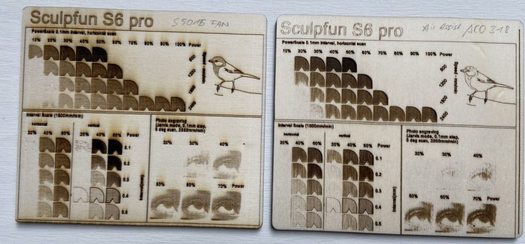
The next question is usually whether there is a library of settings. Rather no. This is simply because every material is different. Every laser as well. And literally from one piece to the next. I read reports almost daily that one sheet of plywood worked great and the next one from the same package didn’t. They are natural materials and there is a lot of variation in production as well. Therefore, there can be no general settings that always work. So, my advice is to feel your way around. Start with higher speed and lower laser power and if you don’t get a satisfactory result, then decrease the speed and / or increase the laser power. You need a test specimen of each material on which you can try out the settings. So-called material test files, which test many settings in one go, also help here. These can be created directly in LightBurn, or you can download one like this: Test file from hobbylasercutters.com (corrected version).
Nevertheless, to give you a few figures:
For engraving, speeds between 1000 and 2000 mm / min are usually quite suitable. In addition, a laser power of about 20-60%.
For cutting, it is usually something like 100-600 mm / min and a laser power of 85%. In addition, you typically need several passes, depending on the thickness of the material. For 10 mm wood, this can mean 30 passes and more! The power of the laser should not be permanently above 90%, this will significantly reduce the life of the diode.
I have created an extended article about this here: Settings Guide.
Focus
It is already stated in the basic documentation, but just as an additional note, here is how you focus the laser. The shield is not fixed in position, but removed at every cleaning cycle. After remounting, it should never touch the workpiece. The air and dirt particles need to escape somewhere. Leave a gap of 3-5 mm to the workpiece. The focus distances are as follows:
| S6, S9 | 20 mm |
| S10 | 50 mm |
| S30, S30 Pro (5W, 10W), S30 Ultra 11W | 50 mm |
| S30 Pro Max (20W), S30 Ultra 22W, 33W, iCube Pro (5W) | 40 mm |
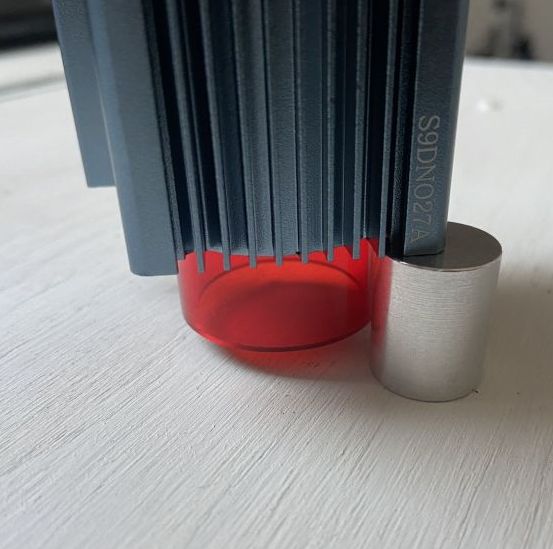
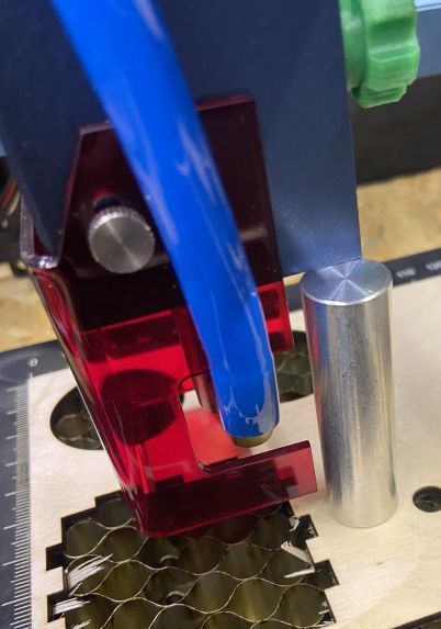
If you lost your tiny focus piece, you can laser new ones yourself. Here is a file containing different pieces for all Sculpfun models: Download (LightBurn file).
Testing
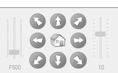
Both LightBurn and LaserGRBL have a function that allows you to move the laser manually. Here you can first test if the connection works and the settings are correct. If you press the arrows for left / right / forward and backward, the laser should move accordingly.
Additionally, LightBurn has an excellent Quick Start Guide to help you through your first project: https://lightburnsoftware.github.io/NewDocs/FirstRun.html
Coordinate System
Update: I collected some condensed information about coordinate systems here.
Another question that is asked continuously is about correctly positioning the laser head. If you have a system without limit switches (the usual case with most cheap laser engravers), your laser does not know where the head is positioned at the start. If you start right away, send a drawing to your laser to start engraving, it might crash into the frame. [The next explanations are based on LightBurn because I use this one most frequently, but also applies to most other tools I think]. Your PC control program and the firmware work with its coordinate system each. LightBurn, for example, takes the lower-left corner of your workspace as [0,0] with x and y pointing to the right and up in positive space. Since the firmware does not know where it is after startup, it treats the startup position as [0,0]. This might be anywhere in the workspace. Best practice in this case is to manually move the laser head to the lowest left corner before turning on (or while resetting → this can be done by right-click on the device button in the Laser Control window). Then your firmware [0,0] position is in the lower-left corner as well. (see LB documentation about coordinates). In these cases, you use “absolute positioning” as setting.
If you know that you’ll stay in the mechanical limits, you can also start right from the point you are and don’t need to move it down left. In either case, you need to select “current position” in LightBurn, which tells the laser to start right off the current position. LightBurn additionally offers the option to select if the object should be drawn from center, top, top-right etc. (9 possibilities, the small radio boxes with 9 options).
To ease the process and get constant repeatability, you can add limit switches to the frame, which enables automated homing, see Extras.
More useful info about coordinate systems can also be found in the LB documentation: https://lightburnsoftware.github.io/NewDocs/CoordinatesOrigin.html
Troubleshooting
If the laser does not work as expected after going through these steps, there might be some other problems. First, check the mechanical setup (guide is here). Next, check if your question is answered in the FAQ section. LightBurn also released a video on common problems (more related to Ortur devices, but most tips also apply here):
Software Piracy
LightBurn is one of the most popular software tools for lasering. It contains a lot of ingenious features and is very cheap for that. You should not try to get it even cheaper by acquiring license keys from dubious or private sources. These are often not legal. LightBurn has an ingenious function to make stolen versions recognizable: The output to the laser is disturbed. Either text is lasered that you didn’t set, or the shapes are pieced. This is not a hardware or setup problem, it is intentional. The development of these tools costs time and money, and the developers deserve to be paid for it! If you can afford a laser for more than $300, you can also spare the $60 for a license.

Merci pour cet article très détaillé.
Comments are closed.